Three Common PCB Copper Plating Process Methods and Their Pros & Cons
In printed circuit board (PCB) manufacturing, copper electroplating is a critical process used to form reliable conductive pathways on the PCB surface and within plated through-holes (PTH). The selection of plating technology directly impacts product reliability, manufacturing costs and lead times.
This guide covers copper plating fundamentals, the three widely adopted PCB copper plating workflows, step-by-step procedures, technical considerations, plus pros and cons for each method.It also explains why SQPCB, equipped with advanced in-house production capabilities, serves as a reliable partner for global B2B customers requiring strict quality and delivery control.
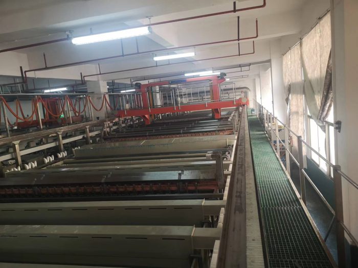
PCB Copper Plating Process
Understanding the Basics: Electroless Copper vs. Electrolytic Copper
Electroless Copper (沉铜)
Electroless copper deposition is a chemical process that deposits an ultra-thin copper layer (typically 0.1–0.3 μm) on non-conductive surfaces, primarily the inner walls of drilled holes and PCB laminate. It forms a conductive seed layer, enabling electric current flow for the subsequent electrolytic plating step.
Electrolytic Copper Plating (电镀铜)
Electrolytic copper plating is an electrochemical process employing a plating bath and direct current to deposit copper over the seed layer. Within PCB production, copper thickness can be precisely regulated. Primary plating (一次铜) generally builds 7–10 μm of copper, and further plating cycles help reach the target final copper thickness.
1. Three Common PCB Copper Plating Processes in pcb manufacturing process
1.1 Thick Copper First → Outer Layer Imaging → Copper & Tin Plating → Resist Strip → Etching → Tin Strip
Steps:
Electroless Copper (0.1–0.3 μm) – Deposits the initial conductive seed layer on hole walls and PCB surfaces.
Full-Panel Electrolytic Copper Plating (Thick Copper) – Builds substantial copper thickness over the entire panel, typically 18–25 μm, to form a robust copper base and reliable PTH walls.
Outer Layer Dry Film Lamination – Applies a photosensitive resist dry film.
Exposure & Development – Transfers the circuit pattern via phototools or LDI (Laser Direct Imaging).
Pattern Copper Plating – Electroplates the exposed circuit traces up to the target finished copper thickness.
Tin Plating – Deposits tin on traces to serve as an etching resist.
Resist Strip – Strips away dry film to reveal unwanted bare copper.
Etching – Removes exposed bare copper from non-circuit regions.
Tin Strip – Removes the tin mask, exposing the final copper circuitry.
Best For: Automotive PCBs, power boards, applications requiring high copper uniformity.
1.2 Thin Copper → First Copper Plating → Outer Layer Imaging → Second Copper & Tin Plating → Resist Strip → Etching → Tin Strip
Steps:
Electroless Copper (0.1–0.3 μm) – Forms the initial conductive seed layer.
First Copper Plating (一次铜 7–10 μm) – Deposits moderate base copper across the entire panel.
Outer Layer Dry Film Lamination – Applies photoresist dry film.
Exposure & Development – Define circuit patterns.
Second Copper Plating – Builds copper on circuit traces up to the target finished thickness.
Tin Plating – Deposits tin to protect traces during the etching process.
Resist Strip – Removes photoresist from non-trace regions.
Etching – Strips away unwanted bare copper.
Tin Strip – Removes the tin mask to reveal the completed circuitry.
Best For: High-density interconnect (HDI) boards, telecom boards, designs requiring precise fine copper thickness control.
1.3 Thin Copper → Thick Copper Plating → Outer Layer Imaging → Etching → Resist Strip
Steps:
Electroless Copper (0.1–0.3 μm) – Forms the initial conductive seed layer.
Full-Panel Thick Copper Plating – Electroplates directly to the required finished copper thickness across the whole panel.
Outer Layer Dry Film Lamination – Applies photoresist dry film.
Exposure & Development – Define circuit traces.
Etching – Removes unwanted bare copper; this process skips the tin plating step.
Resist Strip – Strips dry film from circuit traces.
Best For: Simple layouts, high-current PCBs, and thick-copper designs where ultra-fine features are not critical.
2. Pros and Cons of Each Process
| Process | Advantages | Disadvantages | Applications |
|---|---|---|---|
| Thick Copper → Pattern Plating → Tin | High PTH reliability, uniform outer copper thickness | More steps, longer cycle, higher copper consumption | Automotive, power electronics |
| Thin Copper → First & Second Copper Plating | Flexible control over copper build-up, suited for fine traces | Requires precise process control, more plating stages | HDI, telecom |
| Thin Copper → Full Thick Copper → Etch | Fewer steps, cost savings (no tin plating/strip) | Not ideal for fine lines, higher side-etch risk | Power boards, simple layouts |
3. Why Choose SQPCB for Copper Plating PCBs
Copper plating is only as good as the equipment and process control behind it. Many PCB failures—such as uneven copper thickness, poor solder mask adhesion, or via barrel cracking — can be traced back to insufficient plating quality.
SQPCB stands out by investing heavily in modern inline automation, including:
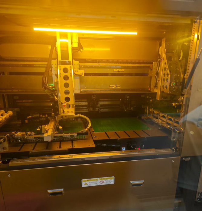
LDI direct imaging for lines – Eliminates distortion from film-based imaging, ensures fine line accuracy.
LDI direct imaging machine for solder mask – Reduces misalignment, improves solder mask clearance, and enhances surface appearance.
Automated inkjet legend printing – Avoids operator errors, scratches, and foreign matter contamination
.
These investments guarantee high yield, reduced rework, and improved solder mask gloss compared with traditional equipment.
Additionally, SQPCB runs its own lamination, HASL, and ENIG plating lines in-house. This not only ensures consistent quality and stable lead times, but also offers customers greater flexibility for urgent or custom orders. For B2B buyers, partnering with a supplier that controls the full process chain means lower risks, faster turnaround, and predictable quality.
SQPCB’s Advantages in Practice:
By deploying advanced inline LDI imaging and fully in-house plating lines, SQPCB eliminates classic manufacturing risks including film shrinkage, misregistration, manual handling errors, and uneven copper deposition. This ensures every plated through-hole and copper trace delivers reliable performance for high-demand applications such as automotive electronics, telecom infrastructure, and industrial control systems.
4.The Business Impact of Choosing the Right Plating Process
From a B2B perspective, selecting the proper copper plating process — and the right manufacturing partner — directly impacts:
Reliability: Eliminating hidden defects that could trigger costly product recalls.
Cost Efficiency: Minimizing scrap and rework through precise process control.
Scalability: Supporting prototype builds and high-volume mass production with consistent quality.
Speed: Achieving shorter cycle times by streamlining redundant process steps.
Global OEMs and EMS providers face ongoing pressure to cut costs without compromising product reliability. Partnering with a manufacturer such as SQPCB, equipped with advanced machinery and full in-house process control, helps businesses gain a strong competitive advantage.
5.Future Trends in PCB Copper Plating
As electronic technology continues to evolve, PCB copper plating processes keep advancing to match higher requirements:
Pulse Plating Technology: Delivers uniform copper distribution within microvias and fine circuit features.
Eco-Friendly Chemistry: Cuts down hazardous waste output and boosts manufacturing sustainability.
High Aspect Ratio Plating: Enables production of sophisticated HDI boards featuring multi-layer stacked microvias.
Automation & Data Control: Industry 4.0 smart factories implement real-time monitoring for plating baths and copper deposition rates.
SQPCB stays ahead of these industry trends. We deploy automation and advanced imaging systems to meet next-generation PCB requirements.
6. FAQs
Q1: What is the difference between electroless and electrolytic copper plating?
Electroless plating is a chemical process used to form the initial conductive seed layer (0.1–0.3 μm). Electrolytic plating relies on electric current to build up the required copper thickness.
Q2: How thick is the first copper plating in PCB manufacturing?
The first copper layer is typically 7–10 μm, creating a stable foundation prior to pattern plating.
Q3: Which process is best for HDI PCBs?
The thin copper → first copper → second copper sequence delivers superior copper thickness control for fine-pitch designs.
Q4: Does Shuoqiang perform copper plating in-house?
Yes. SQPCB completes all plating processes internally, guaranteeing consistent quality and shortened lead times.
Q5: How does copper thickness affect PCB performance?
Thicker copper enhances current-carrying capacity and thermal dissipation, yet it raises production cost and can restrict fine trace fabrication capability.

- Special PCB
- long board pcb
- Flexible PCBs
- Special PCB
- Express Printed Circuit Board
- Pcb Prototype
- LED PCB
- PCB
- Printed Circuit Board
- Pcb Meaning
- Pcb manufacturer
- Rigid pcb board
 Quote
 E-mail