1. Introduction to Rogers 5880 and Its Thickness Options
Rogers RO5880 is a high-frequency laminate from Rogers Corporation, known for its exceptional dielectric properties, low signal loss, and mechanical stability. It’s especially favored in microwave, RF, and aerospace applications, where signal integrity and thermal stability are critical.
What sets Rogers 5880 apart is its low dielectric constant (Dk ≈ 2.2) and ultra-low dissipation factor (Df ≈ 0.0009 @ 10GHz), making it ideal for high-frequency PCB applications where performance cannot be compromised.
The thickness options available for Rogers 5880 provide designers with the flexibility to optimize for electrical performance, mechanical needs, and cost.
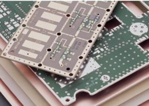
Rogers RO5880
2. Understanding Rogers 5880 Dielectric Properties and Applications
2.1 Key Properties of Rogers 5880
-
Dielectric constant (Dk): 2.2 ±0.02
-
Dissipation factor (Df): 0.0009 at 10GHz
-
Thermal coefficient of Dk: +53 ppm/°C
-
Moisture absorption: 0.02%
-
Tg (glass transition temperature): >200°C
2.2 Common Applications of Rogers 5880
-
Aerospace communication systems
-
High-frequency antennas and radar
-
RF and microwave circuits
-
Satellite and defense technology
-
Phase-sensitive analog circuits
The low moisture absorption and mechanical stability make Rogers 5880 particularly suitable for outdoor and mission-critical environments.
3. Exploring Available Rogers 5880 Thickness Options
Rogers 5880 is manufactured in multiple thicknesses to meet varied design needs. Standard thickness options include:
| Thickness (inches) | Thickness (mm) | Copper Cladding Options |
|---|---|---|
| 0.005″ | 0.127 mm | 0.5oz/1oz rolled or electrolytic |
| 0.010″ | 0.254 mm | 0.5oz/1oz |
| 0.020″ | 0.508 mm | 0.5oz/1oz/2oz |
| 0.030″ | 0.762 mm | 1oz/2oz |
| 0.060″ | 1.524 mm | 1oz/2oz |
The selection of thickness impacts many critical parameters — signal loss, mechanical integrity, thermal behavior, and cost.
4. Rogers 5880 Thickness Options and Signal Loss Considerations
One of the primary drivers behind choosing a particular thickness is insertion loss. As the substrate thickness increases, microstrip line width must also increase for impedance matching, which can result in more copper loss.
However, thicker laminates reduce dielectric losses due to increased separation from the ground plane.
Trade-off Summary:
-
Thinner substrates: Lower copper loss, more dielectric loss
-
Thicker substrates: Higher copper loss, less dielectric loss
This balance is critical in RF designs and is usually evaluated using simulation software such as HFSS or ADS.
5. Rogers 5880 Thickness Options and Mechanical Flexibility
Mechanical flexibility is essential in applications like flex-to-install microwave modules. Thinner options, such as 0.005″ and 0.010″, offer excellent bending capabilities and are suitable for compact or curved assemblies.
Thicker laminates, while offering better rigidity, may crack under stress or require larger enclosures.
6. Rogers 5880 Thickness Options and Cost-Efficiency Trade-offs
From a cost standpoint, thinner laminates are generally less expensive in terms of raw material. However, they may lead to higher fabrication complexity, particularly in multi-layer boards.
On the other hand, thicker boards may increase material cost but reduce labor costs due to better handling and lower risk of warping.
For cost-sensitive designs, it’s crucial to optimize not just material cost but the total cost of ownership, including yield and scrap rates.
7. How to Choose the Optimal Rogers 5880 Thickness Option for Your Application
When selecting a Rogers 5880 thickness, consider the following:
-
Operating frequency: Higher frequencies favor thinner substrates.
-
Power handling: Thicker laminates spread heat better.
-
Bend radius: Flexibility needed?
-
Connector type: Some connectors require specific thicknesses.
-
Stackup design: In multilayer PCBs, how does thickness fit into the overall profile?
Consulting with experienced PCB manufacturers like SQ PCB can simplify this process. Their engineering teams help evaluate the electrical and mechanical constraints of your specific application and suggest the best-fit thickness.
8. Environmental and Reliability Factors for Rogers 5880 Thickness Options
Designers must also consider environmental reliability:
-
Thinner substrates are more prone to moisture migration unless laminated properly.
-
Thermal expansion is lower in thicker laminates, improving dimensional stability.
-
Rogers 5880 has low outgassing properties, making it suitable for aerospace and space applications.
9. Design for Manufacturability (DFM) and Rogers 5880 Thickness Options
DFM considerations are critical when working with Rogers 5880:
-
Etch compensation is more critical in thinner cores
-
Lamination cycles may differ depending on thickness
-
Drilling tolerances must be adjusted based on core rigidity
Ensuring alignment between design intent and manufacturing capability will ensure a successful outcome.
10. Integration with High-Frequency Components and Rogers 5880 Thickness Options
The substrate thickness can influence component pad designs and performance:
-
SMA connector pads need specific dielectric heights
-
Passive filter integration requires careful tuning with thickness
-
High-frequency op-amps and MMICs perform differently across thicknesses
11. Impacts of Rogers 5880 Thickness on Antenna Design
In patch antennas:
-
Thinner substrates yield smaller antennas with lower efficiency
-
Thicker laminates improve bandwidth and gain but may introduce surface waves
Antenna designers often test multiple thicknesses to achieve a balance between performance and size.
12. RF Circuit Optimization and Rogers 5880 Thickness Options
Transmission line structures such as microstrip, stripline, and CPW are sensitive to substrate thickness. Adjusting thickness alters:
-
Impedance
-
Coupling coefficient
-
Return loss
Optimization often requires iterative tuning — a process accelerated by working with vendors like SQ PCB who understand RF nuances.
13. Industry Standards and Certification Considerations of Rogers 5880
When using Rogers 5880 in regulated industries:
-
IPC-6018 for high-frequency boards
-
MIL-PRF-31032 for military
-
RoHS and REACH for environmental compliance
Thickness affects not just the electrical properties but also testability and compliance pathways.
14. Summary of Key Considerations for Rogers 5880 Thickness Selection
| Factor | Thin Option (0.005″–0.010″) | Thick Option (0.030″–0.060″) |
|---|---|---|
| Signal Loss | Moderate | Low |
| Flexibility | High | Low |
| Cost | Low Material / High Fabrication | High Material / Low Fabrication |
| Thermal Stability | Medium | High |
| Connector Compatibility | Standard | Enhanced |
No one-size-fits-all solution exists — simulation, prototyping, and collaboration are key.
15. Comparing Rogers 5880 Thickness Options with Other High-Frequency Laminates
When choosing among high-frequency laminates, designers often compare Rogers 5880 with alternatives like:
-
Rogers RO3003
-
Taconic RF-35
-
Isola Astra MT77
-
Panasonic Megtron 6
15.1 Electrical Comparison
| Material | Dk | Df | Max Temp | Moisture Abs. |
|---|---|---|---|---|
| Rogers 5880 | 2.2 | 0.0009 | >200°C | 0.02% |
| RO3003 | 3.0 | 0.0013 | >200°C | 0.04% |
| RF-35 | 3.5 | 0.0018 | 200°C | 0.06% |
| Astra MT77 | 3.0 | 0.0017 | 200°C | 0.05% |
Rogers 5880 stands out for ultra-low Dk and lowest Df, making it the ideal choice for systems where every dB of loss matters.
15.2 Thickness Availability
Few laminates match the range of available thickness options provided by Rogers 5880. Its standardization across the industry also means better support and lower tooling costs during fabrication.
Summary: Making the Right Choice with Rogers 5880 Thickness Options
Selecting the right Rogers 5880 thickness is not a trivial checkbox — it is an engineering optimization problem, where electrical, mechanical, and economic factors must be weighed together.
Key Takeaways:
-
Rogers 5880 offers industry-leading electrical performance
-
Thickness options range from 0.005″ to 0.060″
-
Thinner options (0.005″–0.010″) suit flexible, high-frequency, lightweight applications
-
Thicker laminates (0.030″–0.060″) benefit thermal, mechanical, and high-power systems
-
Partnering with a qualified manufacturer like SQ PCB ensures your design is manufacturable and robust
If you are designing for tomorrow’s wireless world, Rogers 5880 — in the right thickness — will not only meet your needs but exceed your expectations.
Frequently Asked Questions (FAQs)
1. What is the difference between rolled copper foil and electrolytic copper foil?
Rolled copper foil is produced by mechanically rolling copper into thin sheets, offering better surface quality and mechanical strength. Electrolytic copper foil is deposited via an electrolytic process and is more flexible and cost-effective.
2. Can I use Rogers 5880 in multilayer stackups?
Yes, but it must be bonded using compatible low-loss prepregs. Compatibility and proper lamination cycles must be confirmed with your fabricator.
3. How do I control impedance when changing thickness options?
Use simulation tools and impedance calculators. Adjust trace width to compensate for dielectric thickness.
4. Is Rogers 5880 suitable for high-power RF circuits?
Yes, especially the thicker variants (0.030″+) that offer better thermal management and dielectric breakdown resistance.
5. Does Rogers 5880 absorb moisture?
Very minimally (0.02%). It’s ideal for outdoor and aerospace environments due to its hydrophobic nature.

- long board pcb
- Flexible PCBs
- Special PCB
- Express Printed Circuit Board
- Pcb Prototype
- LED PCB
- PCB
- Printed Circuit Board
- Pcb meaning
- Pcb manufacturer
- Rigid pcb board
- Rigid Flex PCB
 Quote
Quote
 E-mail