1. Introduction: Mission-Critical Reliability and the Role of Military Circuit Boards
In modern defense and aerospace systems, mission-critical reliability is not a luxury—it is an absolute requirement. Military equipment must operate in environments where the cost of failure is not merely financial but strategic, and sometimes even existential. At the heart of this operational reliability lies an unsung hero: the Military Circuit Board.
Unlike consumer electronics, which can tolerate occasional malfunctions, Military Circuit Boards must deliver uncompromising performance under the harshest conditions—whether that means extreme temperature variations, high-vibration environments, or exposure to radiation and electromagnetic interference. Their role extends far beyond power distribution and signal routing. They represent the foundation upon which military communications, navigation, weapons guidance, aerospace avionics, and radar systems are built.
When we examine the mission profiles of advanced fighter jets, naval warships, or missile defense systems, we see that Military Circuit Boards are designed to serve as the invisible nervous system—transmitting instructions, managing power, and ensuring synchronized operation across highly complex electronic architectures.
I find it personally fascinating how engineers balance performance with resilience in these systems. Unlike in consumer-grade PCB design, where cost and speed-to-market dominate, military PCB design elevates longevity, resistance, and compliance with international defense standards to the top of the priority list. This reorientation changes the way materials are selected, how boards are manufactured, and how they are tested before deployment.
In this article, we will delve deeply into every aspect of Military Circuit Boards—their design principles, material requirements, testing regimes, and future innovations. Along the way, I will share some reflections on why uncompromising performance in this domain is not just a technical standard but a strategic imperative.
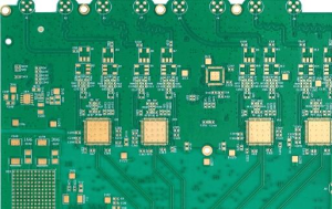
Military Circuit Boards
2. Historical Evolution of Military Circuit Boards
The journey of Military Circuit Boards is deeply intertwined with the evolution of warfare, electronics, and global security priorities. To appreciate the present-day requirements of uncompromising reliability, it is essential to understand how these boards have developed over the past century.
2.1 Early Beginnings: From Vacuum Tubes to Primitive Circuitry
The earliest military electronics during World War II relied heavily on vacuum tube technology. These devices were bulky, fragile, and extremely power-hungry, yet they represented a giant leap in communications and radar. Circuit interconnections were made manually, often with point-to-point wiring or simple substrates. At this stage, there was no concept of a Military Circuit Board as we know it today. Instead, technicians created large assemblies that could barely withstand the vibration of aircraft or the salt-laden air of naval ships.
Despite their limitations, these early circuits demonstrated the potential for electronic dominance in the battlefield. In my view, it is remarkable how quickly military strategists recognized that electronic superiority would soon become as decisive as firepower itself.
2.2 The Cold War Era: The Rise of Printed Circuit Boards
The post-war period saw the emergence of printed circuit board (PCB) technology. During the Cold War, when global powers were investing heavily in missile guidance, nuclear deterrence systems, and advanced communications, the need for Military Circuit Boards became clear.
The first-generation military PCBs were relatively simple, typically single- or double-sided, with through-hole components soldered onto copper traces. Their advantage over earlier hand-wired assemblies was twofold:
-
Consistency – They could be manufactured in standardized formats.
-
Durability – Boards could withstand shock and vibration better than fragile wiring.
This was also the era when military standards such as MIL-SPEC began shaping how electronics were designed and tested. Engineers started realizing that survival in harsh conditions required not just functional circuitry but boards specifically engineered for defense environments.
2.3 The Digital Revolution: Integrated Circuits and Multilayer Boards
The late 20th century marked a digital revolution. The introduction of integrated circuits (ICs) and the demand for higher-density electronics drove the transition from simple two-layer boards to multilayer Military Circuit Boards.
By embedding multiple copper layers and using plated through-holes, engineers could achieve:
-
Higher signal integrity
-
Reduced electromagnetic interference (EMI)
-
Greater miniaturization for compact missile, avionics, and satellite systems
This era also introduced flex and rigid-flex PCBs, which allowed for bending and folding within tight aerospace enclosures. The military quickly adopted these technologies for applications in guided missiles, space exploration, and portable communication devices.
One of my reflections here is that while the consumer electronics sector was also benefiting from multilayer PCBs (think of early computers), the military’s demands for extreme reliability and ruggedness were always ahead of civilian needs. In essence, defense applications drove many of the innovations that later filtered into mainstream electronics.
2.4 21st Century: High-Density Interconnect and Beyond
Today, Military Circuit Boards have reached an extraordinary level of sophistication. The adoption of high-density interconnect (HDI) PCBs, with microvias and laser drilling, has enabled unprecedented functionality within compact form factors.
In modern unmanned aerial vehicles (UAVs), electronic warfare systems, and fifth-generation fighter jets, circuit boards must handle:
-
High-speed data transmission
-
Advanced power distribution networks
-
Resistance to wide temperature fluctuations (from arctic cold to desert heat)
-
Protection against radiation in space applications
What makes today’s boards unique is not only their complexity but the rigorous testing and traceability standards applied to them.
2.5 Reflection: The Unseen Backbone of Defense Technology
From crude wiring in World War II to advanced HDI multilayer designs, Military Circuit Boards have evolved into one of the most strategic enablers of modern defense systems. While missiles, aircraft, and submarines capture public imagination, their effectiveness would collapse without the invisible reliability of military-grade PCBs.
It is my belief that the next chapter in this evolution will likely include embedded artificial intelligence at the PCB level, enabling self-monitoring and predictive failure detection. Just as the past century has shown, the future of defense electronics will continue to be written on copper and laminate substrates, invisibly safeguarding mission-critical reliability.
3. Structural Design Principles of Military Circuit Boards
The design of Military Circuit Boards is not merely a matter of arranging traces and components for functionality; it is a discipline shaped by mission requirements, environmental stress factors, and stringent defense standards. Unlike commercial boards, which optimize for cost or consumer convenience, military PCBs prioritize uncompromising reliability, redundancy, and resilience.
3.1 Layer Stack-Up Design in Military Circuit Boards
At the core of military PCB design lies the layer stack-up strategy. A typical commercial PCB might use four to six layers, whereas Military Circuit Boards often feature multilayer architectures with 12, 24, or even more layers. These additional layers allow engineers to:
-
Isolate signal layers to reduce crosstalk and electromagnetic interference (EMI)
-
Dedicate ground and power planes for stable power distribution
-
Embed shielding layers for protection against electromagnetic pulses (EMP)
The choice of dielectric materials is also critical. Military designers often select polyimide-based laminates for their exceptional thermal stability, low moisture absorption, and high dielectric strength. Unlike FR-4, which is standard in consumer electronics, polyimide can withstand extreme temperature cycles without delamination.
I personally find the layer stack-up fascinating because it illustrates how military engineers view the PCB as a system-level asset, not just a passive interconnect platform. The stack-up essentially becomes an invisible architecture that ensures data integrity and system survivability under stress.
3.2 Signal Integrity in Military Circuit Boards
For mission-critical applications, signal integrity (SI) is paramount. High-speed communication between radar modules, avionics systems, or weapons guidance electronics cannot tolerate skew, jitter, or attenuation. To guarantee SI, military PCB designs employ:
-
Controlled impedance routing to maintain consistent signal velocity
-
Differential pair matching for high-frequency signals
-
Via back-drilling to eliminate stubs that could cause reflections
-
Grounded guard traces to suppress noise coupling
Unlike in commercial designs where slight signal degradation might be acceptable, Military Circuit Boards must deliver precise timing synchronization. Even microsecond delays can mean the difference between mission success and catastrophic failure.
3.3 Redundancy and Fail-Safe Design in Military Circuit Boards
Another defining principle is the incorporation of redundancy and fail-safe mechanisms. Military systems are often deployed in environments where repair or replacement is impossible during operation. As a result, circuit boards are designed with:
-
Multiple redundant pathways for critical signals
-
Dual or triple modular redundancy (TMR) to enable error correction
-
Self-diagnostic circuits that monitor health in real-time
For example, in aerospace avionics, redundant PCB channels ensure that if one communication line is disrupted by interference or damage, another can instantly take over without system downtime.
In my opinion, this design philosophy reflects the military mindset of contingency planning—anticipating failure modes and designing around them before they ever occur.
3.4 Mechanical Reinforcement in Military Circuit Boards
Military PCBs are not only designed for electrical reliability but also for mechanical durability. Common techniques include:
-
Thicker copper layers (2–6 oz vs. 1 oz in commercial boards) for both current capacity and structural rigidity
-
Reinforced substrates to resist flexing and cracking under vibration
-
Edge plating to increase structural strength and EMI shielding
-
Rigid-flex combinations that allow the board to fold inside compact enclosures without sacrificing strength
Mechanical reinforcement is especially crucial in applications like missile guidance systems, where intense acceleration forces can subject the PCB to mechanical shock far beyond normal operating limits.
3.5 Thermal Management in Military Circuit Boards
Another structural requirement is efficient heat dissipation. High-power electronic components generate significant thermal loads, and failure to manage heat can compromise mission reliability. Military designs often include:
-
Metal-core PCBs (MCPCBs) for rapid heat conduction
-
Thermal vias that channel heat away from hotspots
-
Embedded heat spreaders made of copper or aluminum
-
Advanced coatings that improve thermal radiation efficiency
In my reflection, thermal management serves as the bridge between electrical design and material science. It is not enough to design a board that works electrically; it must survive thermal stresses that would quickly destroy commercial-grade PCBs.
3.6 Reliability-Centric Layout in Military Circuit Boards
Finally, the overall PCB layout must prioritize reliability over compactness. This can mean:
-
Larger trace widths to reduce the risk of overheating
-
Wider component spacing to prevent arcing in high-voltage scenarios
-
Avoidance of 90-degree trace bends that could weaken signal integrity
-
Strategic placement of decoupling capacitors to ensure power stability
I believe this reflects a deeper truth: military engineering values robustness more than elegance. Where commercial products chase sleek miniaturization, military boards chase survival under duress.
4. Material Science Behind Military Circuit Boards
The performance and reliability of Military Circuit Boards are not determined by circuit design alone. In fact, one of the most decisive factors is the selection of materials. Each component of the PCB—from the substrate to the copper foil and protective coatings—must be carefully engineered to withstand harsh operational environments.
4.1 Substrate Materials in Military Circuit Boards
The substrate provides the mechanical foundation for a PCB. In consumer electronics, FR-4 (fiberglass epoxy laminate) is the dominant choice due to its cost-effectiveness and versatility. However, in Military Circuit Boards, FR-4 is often inadequate because of its limited performance at extreme temperatures and high moisture absorption.
Military designers frequently use:
-
Polyimide laminates – Exceptional thermal stability, supporting continuous operation above 250°C.
-
PTFE (Teflon)-based composites – Provide superior dielectric properties for high-frequency radar and satellite communications.
-
Ceramic-filled substrates – Enhance both thermal conductivity and dimensional stability.
In my opinion, substrate selection is a balancing act. Polyimide is excellent for thermal cycles, but PTFE composites are better for RF performance. Military engineers must often decide whether thermal or electrical properties are the primary mission driver.
4.2 Copper Foil in Military Circuit Boards
Copper is the lifeline of every PCB. For Military Circuit Boards, copper foil quality directly influences electrical conductivity, reliability, and durability. Two main types are used:
-
Rolled Copper Foil (RA copper) – Produced by mechanically rolling copper into thin sheets. It offers smoother surfaces, excellent flexibility, and high fatigue resistance. This makes it ideal for flex and rigid-flex PCBs in aerospace systems.
-
Electrolytic Copper Foil (ED copper) – Manufactured through electro-deposition. It is cost-effective and widely used but has a rougher surface compared to RA copper.
4.3 Surface Finishes in Military Circuit Boards
Surface finishes are applied to PCB pads to protect copper from oxidation and to provide a solderable surface. For Military Circuit Boards, the finish must not only facilitate assembly but also ensure long-term reliability under harsh conditions. Common finishes include:
-
ENIG (Electroless Nickel Immersion Gold) – Provides excellent flatness, corrosion resistance, and wire-bonding capability.
-
Immersion Silver – Good for high-frequency performance but susceptible to tarnishing if not stored properly.
-
HASL (Hot Air Solder Leveling) – Reliable and cost-effective but less suitable for fine-pitch components in modern military electronics.
-
OSP (Organic Solderability Preservatives) – Rare in military PCBs because of limited durability under long-term storage.
From my perspective, ENIG has emerged as the gold standard (literally and figuratively) for military PCBs. Its combination of corrosion resistance and high solderability ensures stability in critical systems like missile guidance and radar arrays.
4.4 Protective Coatings in Military Circuit Boards
Protective coatings, often called conformal coatings, are critical to safeguarding military PCBs from harsh environmental stressors such as humidity, salt spray, chemical contaminants, and dust. Common coatings include:
-
Acrylic coatings – Easy to apply and rework, moderate protection.
-
Urethane coatings – Excellent resistance against moisture and solvents.
-
Silicone coatings – High flexibility and superior performance at extreme temperatures.
-
Parylene coatings – Provide a pinhole-free, highly reliable conformal barrier, ideal for aerospace and medical applications.
I personally find Parylene fascinating because it is applied in vapor form, penetrating every crevice and delivering a uniform, ultra-thin protective layer. For Military Circuit Boards used in unmanned aerial vehicles or satellites, Parylene can be the difference between flawless operation and catastrophic failure.
4.5 Advanced Composite Materials in Military Circuit Boards
In recent years, composite laminates have revolutionized the design of military PCBs. By blending multiple material classes, engineers achieve optimized performance across several dimensions:
-
Metal-core laminates improve thermal conductivity.
-
Carbon-based composites enhance mechanical strength while reducing weight.
-
Hybrid laminates combine PTFE with ceramics to optimize dielectric constant and minimize signal loss at gigahertz frequencies.
The use of hybrid composites is particularly important for radar and electronic warfare applications, where signal integrity at extremely high frequencies is mission-critical.
5. Reliability Testing of Military Circuit Boards
Designing and manufacturing Military Circuit Boards is only part of the challenge. To truly achieve mission-critical reliability, boards must undergo rigorous testing procedures that far exceed the standards of commercial PCBs. These tests simulate the harshest real-world conditions that a military system might encounter in the field—whether deep in the ocean, high in the atmosphere, or in the vacuum of space.
5.1 Environmental Stress Testing in Military Circuit Boards
Environmental stress testing evaluates how circuit boards respond to temperature, humidity, and chemical exposure. For military applications, this includes:
-
Thermal shock tests – Rapid cycling between extreme hot and cold to simulate desert-to-arctic transitions.
-
Humidity exposure tests – Assessing resistance to corrosion and insulation breakdown.
-
Salt fog tests – Simulating marine environments for naval applications.
-
Radiation testing – Ensuring boards can withstand ionizing radiation in space and nuclear scenarios.
I personally believe these tests are not just quality checks—they are stress rehearsals for survival, ensuring that boards can endure conditions far harsher than most people will ever experience.
5.2 Mechanical Stress Testing in Military Circuit Boards
Military PCBs must survive intense mechanical forces such as shock, vibration, and acceleration. Tests include:
-
Drop and impact tests – Ensuring survival after sudden shocks.
-
Vibration tests – Simulating the high-frequency vibrations found in jet engines, tanks, or missiles.
-
Centrifugal acceleration tests – Validating performance under high-G forces experienced by aircraft or ballistic systems.
Unlike commercial electronics that may fail under these conditions, Military Circuit Boards are designed with reinforcement techniques (thicker copper, stronger laminates) precisely to survive these stresses.
5.3 Thermal Cycling and Aging Tests in Military Circuit Boards
Thermal cycling tests expose PCBs to repeated heating and cooling to assess long-term reliability. Aging tests accelerate the degradation process, allowing engineers to predict mean time between failures (MTBF).
This is where the choice of materials—such as polyimide substrates or Parylene coatings—proves its worth. If a board delaminates or solder joints crack under repeated cycles, it is deemed unsuitable for mission deployment.
5.4 Electrical Performance Testing in Military Circuit Boards
Reliability also depends on how well a board performs electrically under stress. Tests include:
-
Impedance control verification – Ensuring consistent high-speed signal transmission.
-
Dielectric withstand voltage (DWV) – Verifying insulation strength under high voltage.
-
Electromagnetic interference (EMI) testing – Ensuring compliance with military shielding standards.
-
Continuity and isolation tests – Detecting opens, shorts, or leakage paths in circuits.
My reflection here is that electrical testing is often underestimated. Many assume that if a circuit powers on, it works—but in defense systems, signal integrity failures measured in nanoseconds can have life-or-death consequences.
5.5 Reliability Standards and Certification in Military Circuit Boards
Testing is performed according to strict military standards such as:
-
MIL-PRF-31032 – General performance specification for military PCBs.
-
MIL-STD-810 – Environmental engineering considerations for equipment durability.
-
IPC-6012DS – Space and military avionics addendum, covering high-reliability PCB fabrication.
Passing these certifications is not optional—it is mandatory for any board entering defense service. This is why not every PCB fabricator can claim to produce military-grade boards; the barrier to entry is high, and only a handful of companies, such as SQ PCB mentioned earlier, consistently meet these demanding benchmarks.
6. Thermal Management in Military Circuit Boards
Heat is one of the most persistent enemies of reliability. In consumer electronics, overheating may cause temporary malfunctions or shorten device lifespan. But in mission-critical applications, thermal failure in Military Circuit Boards can disable navigation systems, disrupt communications, or even compromise weapons guidance. For this reason, thermal management is a central design priority in military PCB engineering.
6.1 The Heat Challenge in Military Circuit Boards
Military systems often operate in environments where conventional cooling methods are insufficient. Consider the following scenarios:
-
Avionics systems exposed to rapid altitude changes, where external cooling air density is low.
-
Naval electronics operating in sealed enclosures, where convection cooling is impossible.
-
Missile guidance PCBs subject to high-G acceleration and aerodynamic heating.
-
Space systems exposed to direct solar radiation and vacuum conditions, where conduction and radiation are the only heat transfer modes.
Unlike commercial boards, Military Circuit Boards are designed to remain operational at temperatures ranging from –55°C to +200°C, with some systems requiring even wider margins.
6.2 Material Solutions for Thermal Management in Military Circuit Boards
Material science plays a pivotal role in thermal management. Common material strategies include:
-
Metal-core PCBs (MCPCBs) – Incorporate aluminum or copper cores to conduct heat away from components.
-
Ceramic substrates – Offer excellent thermal conductivity and minimal thermal expansion.
-
High-Tg laminates – Maintain stability under extreme thermal cycling.
In my view, metal-core PCBs represent one of the most elegant solutions, acting as both an electrical platform and a heat sink simultaneously. However, ceramics are unmatched in terms of dimensional stability when exposed to repeated temperature fluctuations.
6.3 Structural Techniques for Thermal Management in Military Circuit Boards
Beyond materials, the structural design of the PCB contributes to effective heat control. Techniques include:
-
Thermal vias – Vertically channel heat from surface-mounted components into deeper layers or metal cores.
-
Embedded heat spreaders – Copper or aluminum inserts distribute heat evenly across the board.
-
Thicker copper layers – Increase both current capacity and thermal dissipation.
-
Optimized component placement – High-power components are placed near thermal escape paths.
These approaches must be carefully balanced with electrical performance and weight considerations, particularly in aerospace applications.
6.4 Cooling Systems Integrated with Military Circuit Boards
In addition to board-level strategies, many military systems integrate active and passive cooling solutions:
-
Conduction cooling – Directly coupling PCBs with metal chassis for heat transfer.
-
Forced-air cooling – Fans or blowers used in less extreme environments.
-
Liquid cooling – Circulation of coolant fluids for high-density, high-power systems.
-
Phase-change materials – Absorb and release thermal energy during temperature swings.
I find phase-change materials particularly intriguing. They represent a smart thermal buffer, allowing PCBs to “ride out” short bursts of extreme heat without exceeding operational limits.
6.5 Reliability Risks from Poor Thermal Management in Military Circuit Boards
Failure to address thermal challenges can lead to:
-
Solder joint fatigue from repeated expansion and contraction.
-
Delamination of substrate layers under prolonged heat.
-
Electromigration in copper traces, causing shorts over time.
-
Component derating where sensitive ICs operate below peak efficiency.
These risks highlight why Military Circuit Boards are subjected to extensive thermal testing, as discussed earlier in Section 5.
7. Electrical Performance Standards of Military Circuit Boards
While materials and thermal control ensure survival in hostile environments, the true mission of Military Circuit Boards lies in carrying and preserving electrical signals without degradation. Unlike consumer electronics, which may tolerate signal loss or occasional interference, military systems demand absolute precision, speed, and integrity. A corrupted signal in a smartphone means inconvenience; in a missile guidance system, it could mean mission failure.
7.1 Signal Integrity Requirements in Military Circuit Boards
High-speed communication and radar systems rely on signal integrity (SI)—the ability to transmit signals with minimal distortion. Key requirements include:
-
Controlled impedance – Ensuring trace impedance remains constant to avoid reflections.
-
Low crosstalk – Preventing adjacent signals from interfering with each other.
-
Minimal insertion loss – Maintaining signal strength across long trace lengths.
-
Dielectric consistency – Substrate materials must have stable dielectric constants across frequencies and temperatures.
From my perspective, signal integrity is the “language of reliability”. If the signal remains pure, the mission-critical system remains trustworthy.
7.2 Power Integrity in Military Circuit Boards
Power integrity (PI) ensures that sensitive ICs receive stable and clean power delivery. Challenges include:
-
Voltage droop – Prevented by optimized power planes and decoupling capacitors.
-
Ground bounce – Mitigated by multi-layer stackups and solid ground references.
-
Electromagnetic noise – Reduced through careful power distribution network (PDN) design.
In military contexts, power fluctuations can be disastrous. For example, an unstable voltage regulator could cause a radar module to misfire or lose synchronization.
7.3 Electromagnetic Compatibility (EMC) in Military Circuit Boards
Electromagnetic interference (EMI) is a silent disruptor in electronic systems. Military PCBs must comply with strict EMC (electromagnetic compatibility) standards to both:
-
Prevent self-generated interference from disrupting their own circuits.
-
Resist external interference from enemy jamming or nearby equipment.
Design techniques include:
-
Shielding enclosures around critical circuits.
-
Ground stitching vias for EMI suppression.
-
Differential pair routing to cancel common-mode noise.
-
Filtering components at I/O boundaries.
I find EMC fascinating because it’s not just about engineering—it’s about electronic stealth and resilience. A PCB that leaks signals could give away a radar’s position, while one that resists interference could preserve communications during electronic warfare.
7.4 High-Frequency Performance in Military Circuit Boards
Modern defense systems operate at gigahertz frequencies, particularly in satellite communications, phased-array radar, and EW (electronic warfare). High-frequency PCBs must:
-
Use low-loss dielectric materials like PTFE or ceramic composites.
-
Maintain tight trace tolerances for consistent impedance.
-
Minimize via stubs that create reflections at high frequencies.
7.5 High-Power Density Requirements in Military Circuit Boards
Military PCBs often host high-power electronics in compact footprints. Requirements include:
-
Thicker copper layers to carry higher currents.
-
Optimized trace width and spacing to prevent overheating.
-
Dielectric breakdown resistance to withstand high voltages.
This is particularly crucial in applications such as directed-energy weapons and high-power radar, where current densities exceed those of conventional electronics by several magnitudes.
7.6 Standards and Compliance in Electrical Performance
Military PCBs must comply with standards that regulate electrical performance, including:
-
MIL-PRF-55110 – Governing rigid military PCBs.
-
MIL-PRF-50884 – Covering flexible PCBs for military use.
-
IPC-2221/2222 – General PCB design standards with military addenda.
Such standards ensure that every Military Circuit Board speaks the same electrical “language” of reliability, regardless of the mission environment.
8. Testing and Validation of Military Circuit Boards
No matter how well Military Circuit Boards are designed or manufactured, they must endure rigorous testing and validation before deployment. Testing is the bridge between engineering confidence and battlefield certainty—it ensures that what is promised on paper becomes reality under pressure.
8.1 Environmental Stress Testing for Military Circuit Boards
Military PCBs face conditions beyond commercial tolerance. Validation includes:
-
Thermal cycling: Exposing boards to alternating hot and cold extremes.
-
Vibration and shock testing: Simulating missile launches, jet maneuvers, or shipboard impacts.
-
Humidity and corrosion resistance: Ensuring coatings withstand tropical or maritime climates.
Reflection: To me, these tests resemble military boot camps for PCBs—intentionally harsh, so that failures appear in the lab, not the field.
8.2 Accelerated Life Testing of Military Circuit Boards
Instead of waiting for natural aging, engineers simulate years of wear in weeks:
-
High-temperature operating life (HTOL) exposes PCBs to prolonged stress.
-
Power cycling tests repetitive on/off endurance.
-
Accelerated fatigue predicts solder joint reliability.
This proactive approach answers the crucial question: Will this PCB still work after a decade in service?
8.3 Electromagnetic Interference (EMI) and Electromagnetic Compatibility (EMC) Testing
In a battlefield saturated with radio signals, PCBs must:
-
Emit minimal interference that could compromise stealth.
-
Resist external jamming or cross-talk from other systems.
-
Comply with MIL-STD-461 for electromagnetic compatibility.
Reflection: I see EMI/EMC testing as teaching a PCB to stay disciplined in a noisy crowd—to speak clearly without shouting, and to listen without confusion.
8.4 Radiation Testing for Space-Oriented Military Circuit Boards
PCBs intended for satellites or high-altitude drones undergo:
-
Total Ionizing Dose (TID) tests to assess radiation buildup.
-
Single Event Upset (SEU) simulations mimicking cosmic ray impacts.
-
Material degradation studies under solar exposure.
These tests determine whether the board will function in orbit for 15+ years without mission failure.
8.5 Functional and System-Level Testing of Military Circuit Boards
Beyond stress and environment, boards must prove mission readiness:
-
End-to-end functional tests confirm logical operations.
-
System integration validation ensures compatibility with sensors, weapons, and communication links.
-
Field trials put boards in real prototypes under operational conditions.
Here, reliability shifts from component quality to system trustworthiness.
8.6 Documentation and Traceability in Military Circuit Board Validation
Every test result must be:
-
Recorded meticulously for auditing and certification.
-
Linked to specific production lots for traceability.
-
Reviewed under defense compliance protocols to ensure legal and ethical integrity.
Such documentation makes reliability provable, not assumed.
Conclusion — The Silent Backbone of Military Reliability
Across the thousands of words, examples, and reflections explored in this work, one truth emerges clearly: Military Circuit Boards are the silent backbone of mission-critical reliability.
Technology will evolve—AI-assisted design, quantum resistance, flexible substrates, green manufacturing—but the mission-critical requirement will not change. Reliability remains the final word, the uncompromising demand, the true essence of military electronics. In the end, Military Circuit Boards are not just circuits. They are promises kept.
FQA
FAQ 1: How is testing for Military Circuit Boards different from commercial PCB testing?
Military PCB testing is far more extensive. It includes thermal shock, vibration, EMI/EMC, and radiation resilience, whereas commercial PCBs are usually validated only for functionality and limited environmental ranges. Military standards demand proof of survival in extreme, unpredictable conditions.
FAQ 2: Why are Military Circuit Boards called “mission-critical”?
They are “mission-critical” because the success or failure of a mission—whether in air, sea, space, or cyberspace—depends directly on their flawless performance. Unlike commercial electronics, failure in military PCBs is not an inconvenience; it is a matter of national security and human survival.
FAQ 3: What is the difference between rolled copper foil and electrolytic copper foil?
Rolled copper foil is produced by mechanically compressing copper into thin, ductile sheets, providing better flexibility, fatigue resistance, and smoother surfaces. Electrolytic copper foil, on the other hand, is formed via electro-deposition, offering cost efficiency and high availability but with slightly less mechanical strength.
FAQ 4: Why is thermal cycling so important for Military Circuit Boards?
Thermal cycling simulates real-world conditions where electronics expand and contract due to temperature changes. Military environments—like fighter jets or desert operations—see dramatic thermal swings. Without proper testing, solder joints and laminates could fail prematurely, leading to catastrophic system malfunctions.
FAQ 5: What is the difference between thermal vias and heat spreaders in Military Circuit Boards?
Thermal vias are vertical copper-plated holes that conduct heat from hot components to other board layers or heat sinks. Heat spreaders, on the other hand, are embedded copper or aluminum plates that distribute heat laterally across the board. Thermal vias handle vertical conduction, while heat spreaders manage horizontal dissipation.

- long board pcb
- Flexible PCBs
- Special PCB
- Express Printed Circuit Board
- Pcb Prototype
- LED PCB
- PCB
- Printed Circuit Board
- Pcb meaning
- Pcb manufacturer
- Rigid pcb board
- Rigid Flex PCB
 Quote
Quote
 E-mail