1. Introduction to Flex Coverlay PCBs
1.1 Overview of Flex Coverlay PCBs
Flex Coverlay PCBs represent a specialized category of flexible printed circuit boards, designed to provide both mechanical resilience and electrical reliability in dynamic applications. Unlike standard rigid PCBs, flex coverlay boards incorporate a protective polyimide or polymer layer known as a coverlay, which shields the conductive traces from mechanical stress, environmental exposure, and chemical degradation. This combination of flexibility and protection allows these PCBs to endure repeated bending, vibration, and thermal cycling without compromising performance.
Flex Coverlay PCBs are widely used in industries where motion, vibration, or compact design are critical factors. Examples include wearable electronics, medical devices, automotive sensors, and aerospace equipment. The coverlay not only prevents accidental short circuits but also enhances the mechanical integrity of the board, making it suitable for highly dynamic environments.
1.2 Historical Development and Industry Evolution
The evolution of Flex Coverlay PCBs is closely linked to advancements in flexible electronics and materials science. Early flexible circuits were often simple single-layer designs with minimal protective coatings, limiting their reliability under stress. With the introduction of high-performance polyimide coverlays and adhesive systems, manufacturers were able to significantly improve the longevity and performance of flexible circuits.
Over the last few decades, flex coverlay technology has become more sophisticated, integrating multi-layer designs and high-density interconnects while maintaining flexibility. Innovations in fabrication techniques, such as laser drilling, precision etching, and advanced lamination, have expanded the scope of applications for these boards. As electronics continue to miniaturize and devices require more complex mechanical configurations, the role of flex coverlay PCBs has become increasingly critical.
1.3 Common Applications in Dynamic Environments
Flex Coverlay PCBs are particularly well-suited for applications where mechanical movement or environmental exposure is frequent. Some of the most notable applications include:
-
Wearable Electronics: Smartwatches, fitness trackers, and health monitoring devices require circuits that can flex with body movement while maintaining signal integrity.
-
Medical Devices: Catheters, sensors, and diagnostic equipment benefit from flex coverlay boards due to their biocompatibility, flexibility, and reliability in repetitive motions.
-
Automotive Electronics: Advanced driver-assistance systems (ADAS), infotainment displays, and sensor arrays rely on flex coverlay PCBs to withstand vibrations, temperature fluctuations, and tight installation spaces.
-
Aerospace and Defense: In aerospace, electronics must endure harsh conditions including mechanical shock, vibration, and thermal extremes, making flex coverlay PCBs indispensable for avionics and control systems.
The combination of durability, flexibility, and electrical performance makes flex coverlay PCBs the preferred choice in applications where standard rigid or unprotected flexible PCBs would fail.
Flex Coverlay PCBs
2. Structural Features of Flex Coverlay PCBs
2.1 Materials Used in Flex Coverlay PCBs
Flex Coverlay PCBs rely on a combination of advanced materials that provide both flexibility and protection. The primary substrate is typically polyimide, a high-performance polymer known for its excellent thermal stability, mechanical strength, and chemical resistance. Polyimide substrates allow the PCB to bend, twist, and conform to complex shapes without cracking or losing conductivity.
The coverlay is a critical component, usually made from polyimide films bonded with adhesives. This layer protects the copper traces from mechanical damage, moisture, and chemical exposure. The coverlay is designed to withstand repeated flexing while maintaining adhesion, preventing delamination even under dynamic stress.
Copper foils are the primary conductive material, available in rolled copper foil and electrolytic copper foil. Rolled copper foil offers superior surface quality and mechanical strength, while electrolytic copper foil is more flexible and cost-effective. Choosing the appropriate copper type can influence both the mechanical resilience and electrical performance of the flex coverlay PCB.
Additional materials, such as adhesives, solder masks, and reinforcement layers, may be integrated to enhance specific properties. For instance, reinforcement layers are sometimes used in high-stress areas to reduce the risk of fracture at bending points.
2.2 Layer Construction and Mechanical Properties
A typical Flex Coverlay PCB consists of several key layers:
-
Substrate Layer: Provides the flexible base for the PCB, usually polyimide.
-
Copper Layer: Conductive traces etched onto the substrate, typically 18–35 μm thick.
-
Adhesive Layer: Bonds the coverlay to the substrate and copper, ensuring mechanical integrity.
-
Coverlay Layer: Protects the traces from environmental and mechanical damage.
-
Optional Reinforcement Layers: Used in high-stress zones or areas with connectors to prevent cracking.
The mechanical properties of flex coverlay PCBs are crucial for dynamic applications. These boards can tolerate bending radii as small as a few millimeters without failure. Proper design, including careful routing of traces and strategic placement of coverlay openings, ensures that the PCB maintains both flexibility and structural integrity over repeated cycles.
2.3 Thermal and Electrical Performance
Flex Coverlay PCBs are engineered to maintain stable electrical performance under thermal and mechanical stress. Polyimide substrates provide high thermal resistance, typically rated up to 200–250°C, making these boards suitable for soldering and high-temperature environments.
Electrically, the combination of high-quality copper and precise coverlay application ensures minimal signal loss and consistent impedance control, even in high-frequency circuits. Flex coverlay boards can also accommodate multilayer designs, providing enhanced routing density while preserving flexibility.
The interplay between material selection, layer construction, and thermal/electrical properties defines the overall reliability of Flex Coverlay PCBs. By optimizing these factors, engineers can achieve long-lasting, high-performance solutions suitable for wearable electronics, automotive systems, aerospace controls, and more.
3. Advantages of Flex Coverlay PCBs
3.1 Enhanced Reliability in Dynamic Applications
One of the primary advantages of Flex Coverlay PCBs is their exceptional reliability under mechanical stress. The coverlay layer protects the copper traces from bending, stretching, and vibration, significantly reducing the risk of cracks, shorts, or open circuits. This makes them ideal for applications where repeated motion is inevitable, such as wearable devices, robotics, and automotive sensors.
In high-vibration environments like automotive or aerospace systems, conventional rigid PCBs may fail due to mechanical fatigue. Flex coverlay boards, however, absorb and distribute stress across the substrate and coverlay layers, maintaining electrical continuity and structural integrity. This reliability is not only a technical benefit but also reduces maintenance costs and enhances product longevity.
3.2 Flexibility and Space Optimization
Flex coverlay technology allows for more compact and intricate designs, optimizing the use of available space in modern electronics. The boards can bend and fold to fit within confined enclosures, eliminating the need for additional connectors or interposers that may introduce failure points.
The ability to create three-dimensional configurations also enables designers to reduce the overall weight of devices, a critical factor in wearable technology, aerospace electronics, and medical implants. By integrating the protective coverlay, these flexible boards maintain mechanical and electrical performance even when folded or bent repeatedly.
3.3 Electrical Performance and Signal Integrity
Beyond mechanical advantages, flex coverlay PCBs offer stable electrical performance. The precision of copper trace etching, combined with the protective coverlay, ensures low resistance, consistent impedance, and minimal signal degradation. This is particularly important for high-frequency applications such as RF modules, communication devices, and advanced sensors.
Flex coverlay boards also support multi-layer designs, allowing complex routing without compromising flexibility. This means high-density circuits can coexist with dynamic motion capabilities, an essential factor for miniaturized electronics.
3.4 Durability under Thermal and Mechanical Stress
Flex Coverlay PCBs are engineered to withstand both thermal cycling and mechanical stress. Polyimide substrates tolerate high temperatures, while the coverlay layer prevents trace oxidation and environmental damage. This durability ensures the PCB can operate reliably across a wide temperature range and under repeated bending cycles.
Additionally, the combination of flex substrate and coverlay layer distributes mechanical forces more evenly, reducing the likelihood of failure at solder joints or connector interfaces. This performance is critical in demanding applications such as automotive sensors, aerospace controls, and industrial robotics.
4. Impact of Flex Coverlay PCBs on Overall PCB Performance
4.1 Mechanical Stress Resistance
Flex Coverlay PCBs are engineered to withstand repeated bending, twisting, and vibration, significantly enhancing the mechanical robustness of electronic assemblies. Traditional rigid PCBs are prone to micro-cracks and delamination when exposed to dynamic loads, which can lead to intermittent electrical failures. By integrating a coverlay layer, flex PCBs distribute mechanical stress over a wider area, reducing localized strain on copper traces and solder joints.
The mechanical resilience of these boards is particularly beneficial in wearable electronics, robotics, and automotive sensors. For instance, in a smartwatch, the PCB must bend constantly with wrist motion. Flex coverlay technology ensures the traces maintain continuity even after millions of bending cycles, extending the device’s operational life and reliability.
4.2 Thermal Management and Heat Dissipation
Flex Coverlay PCBs also influence thermal performance. Polyimide substrates and coverlay materials have high thermal stability, enabling the PCB to tolerate soldering temperatures and prolonged operation in warm environments. Moreover, these materials offer consistent thermal conductivity, helping to distribute heat generated by active components across the board.
Proper thermal management prevents localized overheating, which could degrade adhesives, copper traces, or electronic components. Consequently, devices equipped with flex coverlay boards demonstrate improved performance under continuous operation and extreme temperature variations.
4.3 Long-Term Performance and Lifecycle Benefits
The combination of mechanical resilience, electrical integrity, and thermal stability makes flex coverlay PCBs superior in terms of long-term performance. Devices that incorporate these boards require fewer repairs, show reduced failure rates, and maintain stable signal performance over time.
For manufacturers, this translates to lower warranty costs, reduced product recalls, and enhanced customer satisfaction. For end users, it ensures that devices such as medical sensors, automotive controllers, and aerospace electronics operate reliably over extended lifespans.
5. Manufacturing Considerations for Flex Coverlay PCBs
5.1 Materials Selection and Sourcing
The performance of Flex Coverlay PCBs begins with careful material selection. The substrate material, typically polyimide, must be chosen for its thermal stability, flexibility, and chemical resistance. Copper foils, either rolled or electrolytic, are selected based on the desired balance between mechanical strength and flexibility. Rolled copper offers higher tensile strength and superior surface uniformity, while electrolytic copper provides enhanced flexibility and cost-effectiveness.
Adhesives and coverlay films are equally critical. The adhesive must maintain strong bonding under repeated bending and thermal cycling, while the coverlay film must resist environmental factors such as moisture, chemicals, and UV exposure. Using high-quality materials ensures long-term reliability and reduces the risk of delamination or trace damage.
5.2 Advanced Fabrication Techniques
Manufacturing flex coverlay PCBs requires precision and advanced fabrication processes. Key steps include:
-
Etching: High-precision chemical or laser etching creates conductive traces with minimal variation, ensuring signal integrity.
-
Coverlay Lamination: Applying the coverlay uniformly is essential for mechanical protection. Vacuum lamination techniques prevent air bubbles and ensure strong adhesion to the copper traces.
-
Drilling and Via Formation: Microvias and through-holes require careful control to avoid damaging the flexible substrate. Laser drilling is often preferred for accuracy and minimal thermal impact.
-
Solder Mask Application: In some designs, solder masks are applied selectively to enhance electrical insulation without compromising flexibility.
Advanced fabrication techniques are necessary to maintain tight tolerances, prevent defects, and ensure the board can withstand repeated mechanical stress.
5.3 Testing and Quality Assurance
Quality assurance is a critical step in flex coverlay PCB manufacturing. Boards are subjected to rigorous testing, including:
-
Mechanical Stress Testing: Simulates repeated bending, folding, and vibration to verify durability.
-
Thermal Cycling: Ensures stability under fluctuating temperatures.
-
Electrical Testing: Confirms continuity, impedance control, and signal integrity.
-
Environmental Exposure: Assesses resistance to humidity, chemicals, and UV light.
6. Design Strategies to Maximize Flex Coverlay PCB Performance
6.1 Layout Optimization
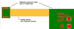
Effective design is essential to maximize the reliability and performance of Flex Coverlay PCBs. One of the key considerations is layout optimization. Designers must strategically place components to minimize bending stress on critical traces. For example, rigid components should be located in low-flex areas, while flexible sections can accommodate traces and smaller components that can tolerate repeated bending.
Optimal spacing between traces is also critical. Adequate spacing reduces the risk of short circuits due to mechanical deformation, while maintaining electrical performance. Designers should also consider signal paths to ensure minimal interference and impedance control, particularly for high-frequency circuits.
6.2 Trace Routing and Coverlay Integration
Trace routing in flex coverlay PCBs requires careful attention to bending radii and stress points. Traces should follow smooth curves rather than sharp angles to distribute mechanical stress evenly. This reduces the likelihood of micro-cracks developing under repeated flexing.
The coverlay must be properly integrated with the traces. Openings in the coverlay should align precisely with pads and vias, ensuring solderability without compromising protection. Selecting the right coverlay thickness is essential: too thin may fail to protect the traces, while too thick can reduce flexibility.
6.3 Mitigating Mechanical Stress in High-Motion Applications
High-motion applications, such as wearable devices, robotics, or automotive sensors, require additional strategies to mitigate mechanical stress. Common techniques include:
-
Strain Relief Zones: Designated areas that absorb bending stress, protecting critical traces and components.
-
Zoning: Separating high-flex and low-flex areas to ensure components in rigid regions are not subjected to repeated bending.
-
Reinforced Areas: Adding localized reinforcement near connectors or solder joints to prevent fracture.
By applying these strategies, engineers can extend the operational life of flex coverlay PCBs and enhance reliability in dynamic applications. Proper design not only prevents mechanical failure but also preserves signal integrity and thermal performance.
Conclusion
Flex Coverlay PCBs have emerged as a cornerstone technology for dynamic and high-performance electronic applications. Their unique combination of flexibility, mechanical resilience, and electrical stability allows them to thrive in environments where traditional rigid or standard flexible PCBs would fail. From wearable devices and medical instruments to automotive sensors and aerospace electronics, flex coverlay boards provide unparalleled durability and signal integrity under repeated bending, vibration, and thermal cycling.
Flex coverlay technology is not merely a design choice—it is a strategic investment in reliability, performance, and future-proofing electronic devices. Whether in wearables, medical instruments, automotive systems, or aerospace electronics, flex coverlay PCBs provide the essential shield that modern electronics require.
Frequently Asked Questions (FAQ)
1. What is the difference between rolled copper foil and electrolytic copper foil?
Rolled copper foil is produced by mechanically rolling copper into thin sheets, offering superior surface quality and mechanical strength. It is ideal for applications requiring durability and minimal surface defects. Electrolytic copper foil, on the other hand, is deposited via an electrolytic process. This type of foil is thinner, more flexible, and cost-effective, making it suitable for complex flex coverlay designs where repeated bending is expected. The choice between rolled and electrolytic copper foil affects both mechanical resilience and electrical performance of flex coverlay PCBs.
2. How do Flex Coverlay PCBs differ from traditional flexible PCBs?
Flex coverlay PCBs differ from standard flexible PCBs primarily through the presence of a protective coverlay layer. While standard flexible PCBs provide basic bending capabilities, the coverlay in flex coverlay boards protects conductive traces from mechanical stress, environmental exposure, and chemical damage. This additional layer significantly enhances reliability in dynamic applications, such as wearables, automotive sensors, and aerospace electronics.
3. Can Flex Coverlay PCBs be used in high-frequency applications?
Yes. Flex coverlay PCBs can be designed for high-frequency applications. Precision in copper trace etching, controlled impedance, and proper coverlay selection ensures minimal signal loss and stable electrical performance even at high frequencies. Proper design considerations, such as trace width, spacing, and coverlay openings, are critical to maintaining signal integrity.
4. What are the typical failure modes of Flex Coverlay PCBs?
Typical failure modes include delamination of the coverlay, trace cracking due to excessive bending, and solder joint failures at high-stress points. Environmental factors such as moisture, chemicals, and temperature extremes can also contribute to degradation. These failure modes can be mitigated through careful material selection, optimized design layouts, stress relief zones, and rigorous quality control during manufacturing.
5. How does coverlay thickness affect Flex PCB reliability?
Coverlay thickness directly impacts the flexibility and protection of the PCB. Thicker coverlay layers provide enhanced protection against mechanical stress, abrasion, and environmental factors, but reduce the board’s overall flexibility. Conversely, thinner coverlay layers increase flexibility but may offer less protection to copper traces. Engineers must balance coverlay thickness with the expected mechanical and environmental demands to achieve optimal reliability.

- long board pcb
- Flexible PCBs
- Special PCB
- Express Printed Circuit Board
- Pcb Prototype
- LED PCB
- PCB
- Printed Circuit Board
- Pcb meaning
- Pcb manufacturer
- Rigid pcb board
- Rigid Flex PCB
 Quote
Quote
 E-mail