1. Introduction to Teflon PCB and Laser Cutting for PCBs
In the realm of modern electronics, the relentless pursuit of higher speed, greater miniaturization, and enhanced reliability places immense demands on printed circuit boards (PCBs). Among the multitude of materials used for PCB substrates, Teflon PCB stands out as a premium choice, especially for applications that require exceptional dielectric properties and thermal endurance.
Polytetrafluoroethylene (PTFE), commonly branded as Teflon, has long been celebrated for its outstanding electrical insulation, chemical inertness, and high thermal stability. These attributes have made Teflon-based PCBs indispensable in fields such as aerospace, telecommunications, radar systems, and high-frequency RF circuits, where standard materials like FR-4 or even Rogers laminates fall short.
Choosing the right PCB material is not simply about durability; it profoundly influences signal integrity, noise reduction, and long-term performance. For engineers and designers working at the cutting edge, the material characteristics of Teflon PCBs translate directly into real-world benefits like reduced signal loss, minimized electromagnetic interference, and reliable operation under extreme conditions.
However, working with Teflon PCBs is not without challenges. Their manufacturing demands sophisticated bonding techniques and precision machining, necessitating collaboration with highly skilled fabricators such as SQ PCB, who specialize in handling advanced materials.
This article dives deeply into the science and application of Teflon PCBs, analyzing how their proven dielectric performance offers a competitive edge in demanding electronic designs. I will also share some personal insights on why integrating Teflon PCBs into your projects can be a transformative decision, and why partnering with experienced manufacturers is essential for success.
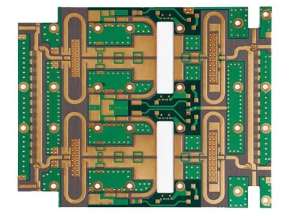
Teflon PCB
2. What is Teflon PCB?
At its core, a Teflon PCB is a printed circuit board that uses polytetrafluoroethylene (PTFE) as its substrate material instead of conventional options like epoxy resin-based FR-4. To understand what sets Teflon PCBs apart, it is crucial to first explore the properties and structure of PTFE itself.
2.1 The Nature of PTFE (Teflon)
Discovered by Dr. Roy Plunkett in 1938, PTFE is a synthetic fluoropolymer composed of carbon and fluorine atoms arranged in a linear chain. This chemical structure confers remarkable stability, low surface energy, and resistance to heat and chemicals.
Key PTFE properties relevant to PCB applications include:
-
Non-reactivity: PTFE does not react with most chemicals, making it highly resistant to acids, bases, and solvents, thereby protecting the PCB substrate from environmental degradation.
-
Low Friction: Its non-stick surface leads to unique challenges in bonding but also contributes to wear resistance.
-
Thermal Stability: PTFE can withstand continuous temperatures up to 260°C and short-term peaks exceeding 300°C, making it ideal for high-temperature PCB processes.
-
Electrical Insulation: PTFE has excellent dielectric properties, with a low dielectric constant (Dk) and dissipation factor (Df), crucial for high-frequency signal integrity.
-
Low Moisture Absorption: It absorbs very little moisture, helping maintain stable electrical characteristics even in humid environments.
2.2 Construction of Teflon PCB
A typical Teflon PCB comprises one or more layers of PTFE substrate laminated with copper foil. However, PTFE’s non-stick property makes conventional lamination difficult. To overcome this, manufacturers use special surface treatments such as plasma etching or chemical roughening to improve adhesion between the copper and PTFE.
Additional layers such as prepregs (pre-impregnated resin sheets) or bonding films may be introduced to enhance mechanical strength and lamination reliability. The copper foil used can be either electrolytic or rolled, depending on the performance requirements and manufacturing capabilities.
2.3 Variants of Teflon PCB Materials
Over time, different grades and composites of PTFE have emerged to balance electrical, mechanical, and processing needs:
-
Pure PTFE Laminates: Offering the best electrical performance but can be mechanically soft and challenging to handle.
-
Filled PTFE: PTFE mixed with glass fiber or ceramic fillers improves mechanical rigidity and dimensional stability while slightly raising dielectric constant.
-
Composite Laminates: These combine PTFE with other materials to tailor thermal expansion coefficients and improve manufacturability.
2.4 Why Use Teflon PCB?
Because of the above properties, Teflon PCBs are especially suited for applications where low signal loss, minimal dielectric heating, and stable performance under temperature extremes are mandatory. This includes RF amplifiers, antennas, microwave circuits, satellite communication modules, and aerospace control electronics.
3. Key Properties of Teflon PCB Material
Understanding the superior performance of Teflon PCB begins with a comprehensive look at the key material properties of polytetrafluoroethylene (PTFE) that make it a favored substrate for high-end PCB applications. These properties underpin why Teflon PCBs maintain signal integrity, thermal resilience, and long-term reliability, especially in demanding environments.
3.1 Low Dielectric Constant (Dk)
The dielectric constant (Dk) measures a material’s ability to store electrical energy in an electric field. A lower Dk means signals propagate faster with less capacitance, which is crucial in high-frequency circuits.
-
Typical Dk Range for Teflon PCB: 2.0 – 2.2
-
Why It Matters: A low Dk reduces signal delay and distortion, helping preserve waveform shape and timing integrity for RF, microwave, and high-speed digital signals.
Compared to traditional materials like FR-4 (Dk ≈ 4.5) or even some high-frequency laminates like Rogers (Dk ≈ 3.2), Teflon PCBs offer significant improvements in signal speed and clarity. This advantage directly translates to better performance in wireless communications, radar systems, and satellite transceivers.
3.2 Low Dissipation Factor (Df)
Dissipation factor (Df) represents the dielectric losses within a material as an alternating electric field is applied. Lower Df values indicate less signal energy is lost as heat.
-
Typical Df for Teflon PCB: As low as 0.0002
-
Impact: Low dielectric loss minimizes signal attenuation, which is critical in circuits where signals travel long distances or at very high frequencies.
This property allows Teflon PCBs to maintain power efficiency and reduce thermal buildup, improving both signal quality and device longevity.
3.3 Excellent Thermal Stability
Teflon’s thermal properties make it suitable for extreme operating conditions:
-
Continuous Use Temperature: Up to 260°C
-
Short-Term Thermal Peaks: Above 300°C
-
Thermal Expansion Coefficient: Moderate, can be adjusted by fillers for better match with copper and other materials.
This thermal stability ensures that Teflon PCBs withstand soldering processes such as reflow and wave soldering without warping, delamination, or loss of electrical characteristics. In environments with fluctuating temperatures or thermal shocks, these PCBs retain mechanical integrity and signal performance.
3.4 Chemical and Moisture Resistance
PTFE’s chemical inertness protects the PCB substrate from degradation by corrosive agents:
-
Resistant to acids, bases, solvents, and oxidizers
-
Extremely low moisture absorption (<0.01%)
Moisture absorption can cause dielectric constant variation and lead to electrical failures like short circuits or corrosion. Teflon PCBs’ resistance ensures stable performance in humid or chemically aggressive environments such as aerospace, marine, or medical applications.
3.5 Mechanical Properties
While pure PTFE is relatively soft and flexible compared to epoxy-based laminates, it still offers:
-
Good dimensional stability when properly filled or reinforced
-
Adequate tensile strength to withstand handling and machining processes
-
Flexibility beneficial in some flexible or rigid-flex PCB designs
Because of the mechanical softness of pure PTFE, manufacturers often use filled or composite variants to improve rigidity without compromising electrical performance.
3.6 Surface Properties and Manufacturing Challenges
PTFE’s surface energy is very low, which gives it a non-stick character. This is excellent for chemical resistance but complicates copper foil bonding. To overcome this, the copper foil or PTFE surface undergoes:
-
Plasma etching
-
Chemical roughening
-
Use of special adhesives or bonding films
These treatments increase surface roughness and promote adhesion. High-precision lamination processes ensure mechanical and electrical integrity of the finished PCB.
3.7 Summary Table of Key Properties
| Property | Teflon PCB (PTFE) | Typical FR-4 | Rogers Laminates |
|---|---|---|---|
| Dielectric Constant (Dk) | 2.0 – 2.2 | ~4.5 | ~3.2 |
| Dissipation Factor (Df) | ~0.0002 | ~0.02 | ~0.0013 |
| Continuous Operating Temp | Up to 260°C | Up to 130°C | Up to 280°C |
| Moisture Absorption | <0.01% | 0.2 – 0.5% | ~0.06% |
| Chemical Resistance | Excellent | Moderate | Good |
| Mechanical Rigidity | Moderate (improvable) | High | Moderate |
| Surface Energy | Very low (non-stick) | Moderate | Moderate |
Personal Reflection
The properties above highlight why Teflon PCB materials are considered the gold standard for high-frequency and harsh environment applications. Their extremely low dielectric constant and dissipation factor ensure signal clarity that other substrates cannot match. Yet, the challenges of handling and manufacturing due to PTFE’s unique surface characteristics mean that only specialized fabricators can reliably produce these PCBs to tight tolerances.
4. Advantages of Using Teflon PCB in High-Performance Electronics
When designing electronics for demanding applications such as aerospace communication systems, radar, satellite transceivers, or 5G wireless devices, the choice of PCB substrate is critical. Teflon PCB materials offer several key advantages that directly contribute to the overall system performance, reliability, and longevity.
4.1 Superior Signal Integrity and High-Frequency Performance
One of the most significant advantages of Teflon PCBs is their outstanding dielectric properties, which directly translate to improved signal integrity.
-
Low dielectric constant (Dk) means signals travel faster and with less distortion, which is essential for RF/microwave frequencies above several gigahertz.
-
Low dissipation factor (Df) minimizes signal loss by reducing dielectric heating and attenuation.
-
Reduced crosstalk and electromagnetic interference (EMI) because of stable dielectric characteristics and uniform substrate quality.
-
Enables higher data rates and bandwidths with less error and noise in sensitive analog and digital signals.
This advantage makes Teflon PCBs the preferred choice for high-frequency circuits such as phased-array antennas, millimeter-wave devices, and radar modules, where signal degradation can critically impact system functionality.
4.2 Thermal Stability Ensures Consistent Operation
Teflon PCB materials maintain structural and electrical integrity under extreme temperature variations.
-
Can handle soldering temperatures and thermal cycling without warping or delamination.
-
Maintains constant dielectric properties even at elevated temperatures, preventing signal drift or impedance mismatch.
-
Enables PCB use in harsh environments such as aerospace, automotive radar, and industrial electronics.
This thermal endurance means devices can operate reliably in scenarios involving rapid temperature changes or prolonged high heat, improving product lifespan and reducing failure rates.
4.3 Chemical and Environmental Resistance
The chemically inert nature of PTFE grants Teflon PCBs excellent resistance to:
-
Corrosion caused by exposure to acids, alkalis, and solvents.
-
Moisture ingress that often leads to electrical failures or decreased insulation resistance.
-
UV exposure and harsh environmental factors in outdoor or aerospace settings.
This resistance minimizes maintenance needs and ensures electrical stability even in corrosive or humid conditions, crucial for mission-critical applications.
4.4 Mechanical Benefits and Dimensional Stability
Although PTFE itself is softer than typical epoxy substrates, filled or composite Teflon laminates provide:
-
Good dimensional stability during manufacturing and in operation.
-
Resistance to mechanical stress, vibration, and shock — important in aerospace and defense electronics.
-
Flexibility that can be advantageous in flex-rigid PCB designs, where bending or folding is necessary without damaging signal integrity.
These mechanical advantages ensure that the PCB maintains precise trace geometries, critical for impedance control and repeatable electrical performance.
4.5 Enhanced Reliability and Long-Term Performance
Because of the combined effects of excellent dielectric properties, thermal and chemical stability, and mechanical robustness, Teflon PCBs deliver:
-
Lower failure rates in fielded devices.
-
Greater resistance to aging effects like delamination, cracking, or signal degradation.
-
Consistent electrical parameters over extended operating life.
This reliability reduces downtime and warranty costs, making Teflon PCB a cost-effective choice for high-end, long-life electronics despite its initial material and processing expense.
4.6 Manufacturing Quality Assurance Impacting PCB Performance
The theoretical benefits of Teflon PCBs can only be fully realized through precise manufacturing processes. Due to PTFE’s non-stick nature and softness:
-
Specialized surface treatments (plasma etching, chemical roughening) must be performed to ensure copper adhesion.
-
Tight control over lamination pressure, temperature, and time is essential to avoid voids or delamination.
-
Accurate drilling and routing with optimized tooling prevents substrate damage.
Choosing a PCB fabricator with proven expertise in Teflon PCB production — like SQ PCB — guarantees these critical steps are rigorously controlled, delivering PCBs that consistently meet or exceed performance specifications.
5. How Teflon PCB Ensures Superior Performance and Quality
The inherent material characteristics of Teflon (PTFE) provide a solid foundation for high-performance printed circuit boards, but it is the synergistic combination of these properties with advanced manufacturing techniques that truly ensures superior PCB quality. In this section, we will dissect how the unique features of Teflon PCB material and state-of-the-art fabrication processes collectively guarantee outstanding electrical performance, mechanical reliability, and long-term durability.
5.1 Intrinsic Material Properties Supporting Performance
5.1.1 Electrical Advantages
-
Low Dielectric Constant (Dk): The low Dk (around 2.0–2.2) minimizes capacitive coupling between adjacent traces and layers, reducing signal delay and preserving waveform integrity. This is critical in high-frequency circuits such as microwave and millimeter-wave devices, where even minor dielectric variations can distort signals.
-
Minimal Dissipation Factor (Df): The extremely low Df (as low as 0.0002) means that dielectric losses are negligible. Consequently, signals can travel longer distances on the PCB without significant attenuation or conversion of energy into heat, preserving power and efficiency.
-
Stable Dielectric Properties Over Temperature and Frequency: Teflon’s dielectric constant and dissipation factor remain relatively constant across wide temperature ranges and frequency bands, ensuring predictable impedance and performance stability.
5.1.2 Thermal and Chemical Stability
-
High Thermal Endurance: The ability to withstand temperatures up to 260°C continuously allows Teflon PCBs to endure soldering processes and harsh operating conditions without substrate degradation or mechanical deformation.
-
Chemical Inertness: Resistance to moisture, solvents, acids, and alkalis protects the substrate from environmental damage that can compromise insulation and cause electrical failure.
Together, these intrinsic material properties create a robust baseline for PCBs designed for demanding applications.
5.2 Advanced Manufacturing Techniques Complementing Material Advantages
While Teflon’s material properties are impressive, they alone cannot guarantee PCB quality. PTFE’s low surface energy causes challenges in adhesion and processing, requiring specialized manufacturing processes:
5.2.1 Surface Preparation and Copper Foil Bonding
-
The non-stick characteristic of PTFE necessitates plasma etching or chemical roughening of the substrate surface before copper lamination to improve adhesion.
-
Use of adhesive bonding films or special primers helps create a strong bond between copper and PTFE.
-
Selecting high-quality copper foil (rolled copper foil preferred for surface uniformity and strength) enhances bonding and reduces micro-voids.
5.2.2 Precision Lamination Process
-
Careful control of lamination temperature, pressure, and time prevents delamination and void formation.
-
Multi-layer Teflon PCBs require sequential lamination with controlled prepregs or bonding films to maintain structural integrity.
5.2.3 Machining and Drilling
-
PTFE’s softness demands optimized drilling parameters (speed, feed, tool type) to avoid burrs or substrate deformation.
-
Use of laser cutting and advanced routing technology improves dimensional accuracy, essential for maintaining trace impedance.
5.2.4 Quality Assurance and Testing
-
Rigorous X-ray inspection, impedance testing, and thermal cycling verify the PCB meets electrical and mechanical specifications.
-
Manufacturers like SQ PCB implement extensive process controls and testing protocols to catch defects early.
5.3 Synergistic Impact on PCB Performance and Reliability
When intrinsic Teflon properties and meticulous manufacturing converge:
-
The PCB exhibits exceptional signal integrity, supporting complex high-speed or RF designs.
-
Mechanical robustness ensures PCBs withstand physical and thermal stresses without performance degradation.
-
Environmental resistance prolongs operational life, reducing downtime and maintenance costs.
-
Consistent impedance control across production batches guarantees repeatable performance in large-scale manufacturing.
6. Applications of Teflon PCB in Modern Electronics
The exceptional dielectric performance, thermal stability, and chemical resistance of Teflon PCBs have made them the substrate of choice across multiple cutting-edge industries. Their ability to maintain signal integrity at high frequencies and withstand harsh environmental conditions enables designers to meet stringent performance and reliability requirements.
6.1 RF and Microwave Communication Systems
One of the primary applications of Teflon PCB materials is in radio frequency (RF) and microwave communication circuits. These systems operate at frequencies where dielectric loss and signal attenuation can severely limit range and data throughput.
-
Satellite communication modules: Require minimal signal loss and precise impedance control for uplink and downlink signals. Teflon PCB substrates reduce distortion, allowing clearer, more reliable transmission.
-
Base station transceivers: In 5G and beyond, where millimeter-wave frequencies are used, Teflon PCBs ensure signal integrity and reduce heat buildup.
-
Radar systems: Military and civilian radar depend on low-loss substrates to maintain resolution and detection accuracy.
6.2 Aerospace and Defense Electronics
Electronics used in aerospace and defense demand components that operate flawlessly in extreme temperatures, vibration, and exposure to chemicals or moisture.
-
Avionics control boards: Benefit from Teflon PCBs’ thermal endurance and chemical inertness, ensuring reliable operation at high altitudes.
-
Guidance and missile systems: Rely on Teflon PCBs for high-frequency signal processing with minimal interference.
-
Satellite payload electronics: Use Teflon substrates to survive launch stress and the harsh environment of space.
6.3 Medical Devices and Instrumentation
Medical electronics require both high reliability and signal accuracy.
-
Diagnostic imaging equipment (MRI, CT): Teflon PCBs provide the stable dielectric environment necessary for sensitive signal processing.
-
High-frequency medical sensors: Use Teflon PCB substrates to maintain low noise and consistent readings.
-
Wearable medical devices: Benefit from the flexibility and chemical resistance of PTFE laminates.
6.4 Telecommunications and Networking Equipment
As data traffic demands explode, telecommunications infrastructure must support higher frequencies and faster signal rates.
-
High-speed routers and switches: Employ Teflon PCBs to minimize signal loss and EMI in complex multi-layer boards.
-
Optical communication transceivers: Use Teflon materials to maintain signal quality over wide frequency ranges.
-
Wireless infrastructure: Benefits from the low dielectric constant to reduce latency and increase bandwidth.
6.5 Automotive Radar and Advanced Driver Assistance Systems (ADAS)
The rise of autonomous vehicles depends on precise, high-frequency radar and sensor systems.
-
Automotive radar modules: Use Teflon PCBs to ensure reliable detection in harsh engine bay environments.
-
LiDAR and sensor fusion circuits: Benefit from PTFE’s thermal stability and signal integrity.
-
Electric vehicle power electronics: Leverage chemical resistance to withstand battery electrolyte exposure.
6.6 Emerging Flexible and Rigid-Flex PCB Technologies
Due to PTFE’s flexibility and chemical stability, Teflon PCBs are increasingly integrated into:
-
Rigid-flex designs: Combining the rigidity needed for connectors with flexible sections for dynamic movement.
-
Wearable electronics: Where bending and chemical exposure require robust substrate materials.
Personal Insight
The widespread adoption of Teflon PCB across such diverse and demanding applications underscores its unique position in the PCB materials hierarchy. From aerospace to medical, Teflon’s ability to maintain pristine signal transmission and physical integrity under stress enables innovation that would be impossible with conventional materials.
Conclusion and Personal Insights
Throughout this comprehensive exploration of Teflon PCB materials, we have seen why PTFE-based substrates remain the gold standard for high-frequency, high-reliability printed circuit boards. Their exceptionally low dielectric constant and dissipation factor, combined with outstanding thermal and chemical stability, empower engineers to design electronics that meet the toughest performance and environmental demands.
Teflon PCBs excel in maintaining signal integrity at microwave and millimeter-wave frequencies, ensuring minimal loss and distortion — a critical factor in aerospace, defense, telecommunications, medical, and automotive radar systems. Their ability to endure harsh temperature cycles and chemical exposure translates into longer lifespans and lower maintenance, despite the initially higher material and fabrication costs.
However, realizing the full benefits of Teflon PCBs requires navigating the unique challenges posed by PTFE’s non-stick nature and softness. This necessitates advanced manufacturing processes including surface treatment, precise lamination, and specialized machining — capabilities that not all PCB fabricators possess.
In summary, while Teflon PCB technology demands careful consideration and investment, its proven dielectric performance makes it an indispensable material for cutting-edge electronics where quality and performance cannot be compromised. For engineers seeking to push the boundaries of high-frequency and high-reliability design, Teflon PCBs offer unmatched advantages — a truth firmly backed by both science and industry experience.
Frequently Asked Questions (FAQ)
1. What is the difference between rolled copper foil and electrolytic copper foil?
Rolled copper foil is produced by mechanically rolling copper into thin sheets, resulting in a foil with superior surface smoothness and higher mechanical strength. This type of foil provides better adhesion and is typically used in high-frequency PCBs such as those based on Teflon substrates.
Electrolytic copper foil, on the other hand, is formed by electrodeposition of copper onto a drum or belt. It tends to be more flexible and less expensive but has a rougher surface. While suitable for many standard PCBs, it may be less ideal for high-frequency Teflon PCBs where surface uniformity impacts performance.
2. How does Teflon PCB compare to Rogers PCB in RF applications?
Both Teflon and Rogers PCB materials are designed for high-frequency applications, but Teflon PCBs typically offer a lower dielectric constant (around 2.0 vs. 3.2 for Rogers) and lower dissipation factor, which translates to reduced signal loss and better performance at very high frequencies.
However, Teflon PCBs are more challenging to manufacture due to the non-stick nature of PTFE and often come at a higher cost. Rogers materials can be easier to process and are preferred when moderate dielectric performance with easier manufacturability is acceptable.
3. Why is adhesion a challenge with Teflon PCB materials?
PTFE’s extremely low surface energy causes copper foil and other layers to have difficulty bonding during lamination. This non-stick property, beneficial for chemical resistance, requires specialized surface treatments such as plasma etching, chemical roughening, or the use of adhesive bonding films to improve adhesion and ensure mechanical stability.
Without these processes, the copper foil may delaminate, leading to electrical failures and reduced PCB reliability.
4. Can Teflon PCBs be used in flexible circuits?
Yes, Teflon PCBs can be used in flexible and rigid-flex circuits due to PTFE’s inherent flexibility and chemical resistance. However, because PTFE is softer and more challenging to handle than typical flexible substrates like polyimide, the design and manufacturing process require careful consideration to avoid mechanical damage during bending or handling.
Advanced fabrication techniques and experienced manufacturers, such as SQ PCB, can successfully produce reliable flexible Teflon PCBs.
5. How do I select the right PCB manufacturer for Teflon PCBs?
When choosing a fabricator for Teflon PCBs, look for:
-
Proven experience with PTFE-based laminates and specialized surface treatment processes.
-
Advanced equipment for plasma etching, precision drilling, and controlled lamination.
-
Strong quality assurance programs with impedance and thermal testing.
-
Track record serving industries requiring high reliability, such as aerospace, defense, and telecommunications.

- long board pcb
- Flexible PCBs
- Special PCB
- Express Printed Circuit Board
- Pcb Prototype
- LED PCB
- PCB
- Printed Circuit Board
- Pcb meaning
- Pcb manufacturer
- Rigid pcb board
- Rigid Flex PCB
 Quote
Quote
 E-mail