1. Introduction to Rogers HDI Boards in High-Frequency PCB Design
In the landscape of modern electronics, high-frequency circuit design presents one of the greatest challenges to engineers. As devices demand faster data transmission, lower loss, and higher integration, traditional PCB materials such as FR4 are increasingly unable to meet these performance requirements. This is where Rogers HDI Boards step in, offering a specialized solution tailored for complex, high-frequency environments.
Rogers Corporation has long been recognized as a global leader in advanced circuit materials, particularly in RF, microwave, and high-speed digital domains. By combining their high-performance laminates with High-Density Interconnect (HDI) technology, Rogers HDI Boards provide the necessary platform for designs that must balance electrical precision, mechanical stability, and miniaturization.
Unlike standard boards, Rogers HDI Boards leverage materials with tightly controlled dielectric constants, low dissipation factors, and excellent thermal stability. This makes them ideal for aerospace, defense, automotive radar, 5G base stations, and cutting-edge consumer electronics. As we navigate the design challenges of tomorrow, these boards are becoming not just an option but a necessity.
From my perspective as someone who has followed both the PCB manufacturing industry and the practical adoption of materials science in electronics, Rogers HDI represents a paradigm shift. It bridges the historical gap between theoretical high-frequency performance and the manufacturability of compact, reliable boards. To put it simply, Rogers HDI Boards are redefining what is possible in circuit engineering.
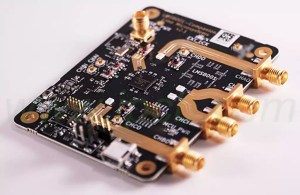
Rogers HDI Boards
2. The Evolution of Rogers HDI Boards in Modern Electronics
The journey of Rogers HDI Boards is not just a story of material innovation, but also one of demand-driven evolution. The electronics industry has consistently pushed toward faster speeds, higher reliability, and smaller footprints. Standard FR4 PCBs, though affordable and sufficient for low- to mid-frequency designs, quickly reached their limits when engineers began to demand GHz-level performance.
Historically, HDI boards emerged as a response to miniaturization trends, especially with the rise of mobile devices. By enabling microvias, fine lines, and thin dielectrics, HDI technology allowed designers to reduce form factors while maintaining or even improving circuit density. However, FR4-based HDI boards still struggled with signal integrity and thermal issues at high frequencies.
This gap led to the integration of Rogers high-frequency materials with HDI techniques, birthing the specialized Rogers HDI Boards. These boards combine the proven mechanical reliability of HDI structures with the superior dielectric performance of Rogers laminates. For engineers, this meant they could design PCBs capable of carrying 10 GHz, 24 GHz, or even millimeter-wave frequencies while still benefiting from HDI’s dense routing and reduced size.
From my perspective, this evolution was inevitable. The industry could not continue to rely solely on low-cost FR4 when the demand for 5G, automotive radar, and IoT systems required higher electrical stability. Rogers HDI Boards answered a crucial question: how do we push performance limits without sacrificing manufacturability? The result has been a smoother pathway for innovation in industries as diverse as defense radar systems and next-generation smartphones.
3. Material Science Behind Rogers HDI Boards
To appreciate why Rogers HDI Boards perform so well, one must understand the material science underpinning them. Rogers laminates, unlike FR4, are not based on glass-reinforced epoxy resin. Instead, they use hydrocarbon-ceramic or PTFE composites, which offer several distinct advantages:
-
Controlled Dielectric Constant (Dk): Rogers materials are manufactured with a tightly regulated dielectric constant, often ranging between 2.2 and 10, depending on the grade. This allows engineers to precisely model and predict signal behavior.
-
Low Dissipation Factor (Df): A low loss tangent ensures minimal signal attenuation, even at high frequencies. This is critical for maintaining data integrity in 5G and radar applications.
-
Thermal Stability: Rogers laminates exhibit stable Dk across temperature variations. This ensures that circuits remain predictable even under harsh operating conditions such as aerospace environments or automotive under-hood electronics.
-
Dimensional Stability: In multilayer builds, the ability of Rogers laminates to resist expansion and contraction is crucial for maintaining layer alignment and via reliability.
When combined with HDI technology, which incorporates laser-drilled microvias, sequential lamination, and advanced copper plating methods, the result is a PCB that is not only electrically superior but also mechanically robust.
In my view, the brilliance of Rogers HDI Boards lies in how they merge material science with process engineering. A good material is useless without a compatible manufacturing method, and HDI processes are what allow Rogers laminates to be utilized effectively in real-world high-frequency designs.
4. Manufacturing Processes of Rogers HDI Boards
The production of Rogers HDI Boards involves several specialized manufacturing steps. Unlike FR4 HDI boards, Rogers laminates demand unique handling due to their chemical and mechanical properties.
-
Lamination: Rogers laminates often require different press cycles compared to FR4, as the resin flow and curing conditions are distinct. Sequential lamination is frequently used in HDI structures, enabling stacked vias and thinner dielectric layers.
-
Microvia Formation: Laser drilling is the method of choice for microvias in Rogers HDI Boards. However, PTFE-based Rogers materials can be challenging to laser-drill cleanly, requiring optimized parameters to avoid resin recast or poor via walls.
-
Copper Plating: Ensuring uniform copper plating within microvias is critical. Since Rogers laminates do not behave identically to FR4 during plating, adjustments in the electroplating chemistry and process are often required.
-
Surface Preparation: Before lamination or plating, Rogers materials require plasma or chemical treatments to enhance adhesion. This is especially true for PTFE-based materials, which are inherently non-stick.
-
Registration and Alignment: With multilayer Rogers HDI Boards, precise registration is critical. Any misalignment in microvias can compromise signal integrity or mechanical stability. Advanced optical alignment systems are therefore essential.
From my perspective, the manufacturing of Rogers HDI Boards is where theory meets reality. It’s one thing to design a high-frequency PCB on simulation software, but quite another to successfully fabricate it. The complexity of processing Rogers laminates explains why not every PCB manufacturer is capable of delivering reliable results.
5. Electrical Performance Advantages of Rogers HDI Boards
One of the strongest arguments for adopting Rogers HDI Boards is their unparalleled electrical performance. Traditional FR4 HDI boards exhibit significant signal loss as frequency increases, primarily due to higher dielectric loss and less controlled impedance. Rogers laminates overcome this limitation by providing low dielectric constant (Dk) variation and exceptionally low dissipation factors.
Key electrical advantages include:
-
Impedance Control: The stable dielectric properties of Rogers laminates allow designers to achieve tight impedance tolerances, which is vital in high-speed differential pair routing.
-
Low Insertion Loss: Rogers materials minimize insertion loss, ensuring signals can travel across longer distances at high frequencies without degradation.
-
Reduced Crosstalk: The uniform dielectric constant reduces unwanted coupling between traces, improving signal isolation.
-
High Frequency Compatibility: Frequencies exceeding 30 GHz, often required in 5G millimeter-wave applications, are achievable with Rogers HDI Boards.
From my engineering perspective, this electrical superiority translates directly into design freedom. Engineers no longer need to overcompensate for material weaknesses through bulky shielding or overly conservative routing. Instead, they can design with confidence that the PCB substrate itself will uphold the intended signal quality.
6. Thermal Management Benefits of Rogers HDI Boards
Another significant advantage of Rogers HDI Boards is their ability to manage thermal challenges. With modern electronic devices packing more components into smaller footprints, heat dissipation has become a serious bottleneck in design reliability.
Thermal benefits of Rogers laminates include:
-
Low Coefficient of Thermal Expansion (CTE): Rogers laminates exhibit CTE values closer to copper, which reduces mechanical stress on vias and solder joints during thermal cycling.
-
Stable Dielectric Properties Across Temperature: Unlike FR4, whose dielectric constant may vary significantly with heat, Rogers maintains consistency, ensuring stable circuit behavior under thermal load.
-
Improved Heat Conduction: Some Rogers materials incorporate ceramic fillers that enhance thermal conductivity, helping dissipate heat more effectively in high-power RF circuits.
From my point of view, the importance of thermal stability cannot be overstated. In automotive radar systems, for instance, PCBs must withstand both hot engine bay conditions and cold startup environments without degrading. Rogers HDI Boards enable this resilience, extending the operating life of the device and reducing field failures.
7. Signal Integrity and Rogers HDI Boards in High-Speed Design
Signal integrity (SI) is arguably the single most important factor in designing modern high-frequency circuits. The challenge lies in maintaining clean signals without reflections, loss, or distortion, especially when data rates push into the tens of gigabits per second.
Rogers HDI Boards contribute to superior SI in the following ways:
-
Controlled Loss Tangent: Low dissipation factor means signals retain their amplitude over longer trace lengths.
-
Consistent Impedance: Variations in dielectric properties directly affect impedance. Rogers materials minimize this variability, allowing engineers to maintain uniform signal performance.
-
Reduced Skew: In high-speed differential signals, skew caused by unequal propagation delays can ruin data integrity. Rogers materials, with consistent electrical characteristics, reduce this risk.
-
Low Electromagnetic Interference (EMI): By maintaining tight impedance and low crosstalk, Rogers HDI Boards help reduce EMI, which is critical in systems like radar and communication networks.
From my perspective, when engineers attempt to push FR4 boards into high-frequency domains, they often end up fighting the material instead of designing with it. With Rogers, the material becomes an ally. This is why more companies in 5G infrastructure and aerospace are making the switch—because they cannot afford unpredictable SI failures.
8. Miniaturization Trends Supported by Rogers HDI Boards
The global electronics market demands devices that are not only faster and more powerful but also smaller and lighter. This trend has fueled the growth of HDI PCBs, and when combined with Rogers materials, the possibilities expand dramatically.
Miniaturization benefits enabled by Rogers HDI Boards include:
-
Microvia Integration: Laser-drilled microvias reduce routing complexity and enable component density that is impossible with traditional through-hole vias.
-
Thinner Dielectric Layers: Rogers laminates allow for ultra-thin dielectric construction, supporting more routing layers in the same board thickness.
-
High Component Density: With consistent electrical performance at reduced dimensions, designers can integrate antennas, RF modules, and digital circuitry in closer proximity.
-
Lightweight Construction: Rogers composites can be lighter than FR4, contributing to reduced overall system weight—a benefit for aerospace and portable devices.
From my point of view, this miniaturization trend is not just about saving space. It is about enabling entirely new applications. For instance, compact radar modules in autonomous vehicles or wearable 5G-enabled devices are only feasible when the PCB can maintain performance in a reduced footprint. Rogers HDI Boards make this possible.
9. Rogers HDI Boards in RF and Microwave Applications
RF and microwave circuits are among the most demanding in the electronics industry. They require substrates that can support precise impedance control, low loss, and stable performance at frequencies often exceeding 20 GHz. This is where Rogers HDI Boards demonstrate their true strength.
Applications include:
-
5G Base Stations: Millimeter-wave antennas and transceivers rely on Rogers laminates to ensure low signal loss and stable propagation.
-
Automotive Radar: Advanced driver-assistance systems (ADAS) use 24 GHz and 77 GHz radar modules, where dielectric stability is essential.
-
Aerospace Communication: Satellite systems and avionics require long-term reliability at high frequencies under extreme conditions.
-
Medical Imaging: MRI and high-frequency diagnostic devices benefit from low-loss Rogers substrates.
From my perspective, the adoption of Rogers HDI Boards in RF and microwave applications marks a turning point in technology. These boards bridge the gap between theoretical electromagnetic design and practical manufacturability, allowing engineers to deliver products that function as intended in the real world.
10. Reliability and Durability of Rogers HDI Boards
Reliability is critical in applications such as aerospace, defense, and medical devices, where failure is not an option. Rogers HDI Boards offer superior long-term durability compared to conventional FR4-based HDI boards.
Reliability benefits include:
-
Thermal Cycling Resistance: Reduced mismatch in CTE between copper and substrate lowers via cracking and pad lifting.
-
Moisture Resistance: Rogers laminates typically absorb less moisture than FR4, maintaining dielectric properties even in humid environments.
-
Mechanical Stability: High dimensional stability prevents warping and misalignment in multilayer builds.
-
Long-Term Electrical Stability: The low Df and stable Dk ensure predictable circuit performance over years of use.
In my view, the real value of Rogers HDI Boards lies not only in peak performance but also in consistent performance over time. A PCB that fails after a few months negates any advantage gained during design. Rogers materials deliver reliability that justifies their premium cost.
11. Comparing Rogers HDI Boards with Traditional FR4 HDI Boards
While FR4 remains the most widely used PCB substrate due to its cost-effectiveness, it cannot compete with the high-frequency performance of Rogers. Comparing Rogers HDI Boards to FR4 HDI boards reveals the trade-offs clearly:
-
Electrical Properties: Rogers offers stable Dk and low Df, while FR4 shows significant loss at high frequencies.
-
Thermal Management: Rogers has lower CTE and better high-temperature performance. FR4 often suffers from expansion mismatch.
-
Moisture Absorption: Rogers absorbs less moisture, maintaining performance in harsh conditions. FR4 can swell and degrade signal quality.
-
Cost: FR4 is significantly cheaper, making it suitable for consumer-grade electronics where extreme performance is unnecessary. Rogers, however, justifies its premium in mission-critical or high-frequency applications.
From my perspective, this comparison is not about declaring one material “better” than the other universally. Instead, it is about application suitability. For GHz-level circuits or radar systems, Rogers HDI Boards are essential. For low-cost consumer gadgets, FR4 remains adequate.
12. Common Mistakes to Avoid with Rogers HDI Boards
Even with the best materials, poor design or manufacturing decisions can compromise performance. Here are some frequent mistakes:
-
Ignoring Material Properties: Treating Rogers the same as FR4 without accounting for Dk/Df differences.
-
Inadequate Simulation: Skipping full-wave simulations at high frequencies, leading to unexpected losses.
-
Improper Stackup Design: Using inconsistent dielectric thickness or poor via design, causing impedance mismatch.
-
Inexperienced Fabricators: Partnering with manufacturers unfamiliar with Rogers processing, leading to low yield.
-
Over-Engineering: Using Rogers laminates where FR4 would suffice, inflating costs without added benefits.
In my view, many of these mistakes stem from underestimating the material’s sensitivity. Rogers laminates provide exceptional benefits, but they demand precision across the entire design and manufacturing chain.
Conclusions
Conquering high-frequency complexity is one of the defining engineering challenges of our time. As data rates rise, devices shrink, and industries demand reliability under extreme conditions, traditional materials like FR4 can no longer keep pace.
Rogers HDI Boards provide the solution:
-
They deliver superior high-frequency performance with low loss and stable dielectric properties.
-
They ensure thermal and mechanical reliability in mission-critical environments.
-
They enable miniaturization through HDI technology while maintaining signal integrity.
-
They create opportunities for innovation across telecom, aerospace, healthcare, automotive, and beyond.
From my perspective, Rogers HDI Boards are not just about better PCBs—they are about enabling the future. Every leap in communication speed, every improvement in medical imaging, every safer autonomous vehicle—these advances are built on the foundation of materials science. And in that foundation, Rogers laminates play an indispensable role.
FAQ
Q: What is the difference between rolled copper foil and electrolytic copper foil?
A: Rolled copper foil is produced by mechanically rolling copper into thin sheets, offering better surface quality and mechanical strength. Electrolytic copper foil is deposited via an electrolytic process and is more flexible and cost-effective. In Rogers HDI Boards, rolled copper foil is often preferred for high-frequency designs due to its smoother surface, which reduces conductor loss at GHz frequencies.
Q: Why are Rogers HDI Boards more expensive than FR4 HDI boards?
A: The higher cost of Rogers HDI Boards comes from several factors: specialized raw materials, complex lamination processes, and tighter quality control standards. While FR4 is suitable for general-purpose electronics, Rogers laminates are engineered for high-frequency, high-reliability applications. The added cost is justified when signal integrity, thermal stability, or long-term reliability are critical.
Q: Can Rogers HDI Boards be combined with FR4 in hybrid stackups?
A: Yes. Hybrid stackups using Rogers laminates for high-frequency layers and FR4 for lower-speed control or power layers are common. This approach balances cost with performance. However, it requires precise lamination control and expertise in managing different material properties such as CTE. Many advanced manufacturers, including those specializing in Rogers HDI Boards, are capable of delivering such hybrid solutions.|
Q: Are Rogers HDI Boards suitable for consumer electronics?
A: Generally, Rogers HDI Boards are not used in cost-sensitive consumer electronics like smartphones or laptops due to higher material and manufacturing costs. However, they are increasingly found in high-end consumer devices requiring strong RF performance—such as premium Wi-Fi routers, advanced drones, or specialized AR/VR headsets. For mass-market devices, FR4 remains the material of choice.
Q: What is the difference between rolled copper foil and electrolytic copper foil?
A: Rolled copper foil is mechanically rolled into thin sheets, offering superior surface smoothness and mechanical durability. This makes it ideal for high-frequency applications on Rogers HDI Boards, where smoother copper reduces conductor loss. Electrolytic copper foil, produced via electro-deposition, is more flexible and cost-effective but has a rougher surface, which can increase signal loss at very high frequencies.

- long board pcb
- Flexible PCBs
- Special PCB
- Express Printed Circuit Board
- Pcb Prototype
- LED PCB
- PCB
- Printed Circuit Board
- Pcb meaning
- Pcb manufacturer
- Rigid pcb board
- Rigid Flex PCB
 Quote
Quote
 E-mail