Polytetrafluoroethylene (PTFE), renowned for its ultra-low dielectric constant and exceptional electrical properties, is a cornerstone material in high-frequency and microwave PCB design. The PTFE dielectric constant, typically ranging from 2.0 to 2.1 across a broad frequency spectrum, makes it indispensable for applications demanding minimal signal loss and high-speed performance. This guide delves into the science behind PTFE dielectric constant, its impact on circuit design, and strategies to leverage its unique properties for cutting-edge electronics.
1. Understanding PTFE and Its Dielectric Properties
1.1 Composition and Structure of PTFE
PTFE is composed of carbon and fluorine atoms, forming a linear polymer chain where each carbon atom is bonded to two fluorine atoms. This unique structure imparts PTFE with remarkable chemical inertness, thermal stability, and low friction. The strong carbon-fluorine bonds contribute to its non-reactive nature, making it suitable for various industrial applications.
1.2 Dielectric Constant of PTFE
The dielectric constant (εr) is a measure of a material’s ability to store electrical energy in an electric field. For PTFE, the dielectric constant typically ranges from 1.8 to 2.1, depending on factors such as frequency, temperature, and manufacturing processes. This low dielectric constant is advantageous in reducing signal delay and minimizing energy loss in electronic circuits.
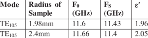
PTFE dielectric constant
2. Factors Influencing the Dielectric Constant of PTFE
2.1 Frequency Dependence
The dielectric constant of PTFE exhibits slight variations with changes in frequency. At microwave frequencies, PTFE maintains a stable dielectric constant, which is essential for consistent signal transmission in high-frequency applications.
2.2 Temperature Effects
PTFE’s dielectric properties remain relatively stable across a wide temperature range. However, at temperatures approaching its melting point (approximately 327°C), slight increases in the dielectric constant may occur due to molecular motion within the polymer matrix.
2.3 Material Processing and Fillers
The incorporation of fillers into PTFE can modify its dielectric properties. For instance, adding glass or ceramic fillers can increase the dielectric constant and mechanical strength, tailoring the material for specific applications.
3. Measurement Techniques for PTFE Dielectric Constant
3.1 Resonant Cavity Method
This technique involves placing a PTFE sample within a resonant cavity and measuring the shift in resonant frequency and quality factor to determine the dielectric constant.
3.2 Transmission Line Method
By analyzing the propagation of electromagnetic waves through a transmission line fabricated with PTFE, the dielectric constant can be extracted from the measured phase velocity and characteristic impedance.
3.3 Split-Post Dielectric Resonator Method
This method uses a dielectric resonator with a split-post design to measure the dielectric properties of thin PTFE samples accurately, especially at microwave frequencies.
4. Applications of PTFE with Specific Dielectric Constants
4.1 High-Frequency Printed Circuit Boards (PCBs)
PTFE’s low dielectric constant is ideal for high-frequency PCBs, ensuring minimal signal loss and consistent impedance, which are crucial for applications like radar systems and RF communication devices.
4.2 Microwave Components
Components such as antennas, couplers, and filters benefit from PTFE’s stable dielectric properties, which contribute to efficient signal transmission and reduced interference.
4.3 Cable Insulation
PTFE is widely used as an insulating material in coaxial cables and other high-frequency transmission lines, where its low dielectric constant helps maintain signal integrity over long distances.
5. Advantages of PTFE’s Low Dielectric Constant
5.1 Signal Integrity
A low dielectric constant reduces signal delay and dispersion, maintaining the integrity of high-speed signals in electronic circuits.
5.2 Reduced Crosstalk
Lower dielectric constants decrease the coupling between adjacent signal traces, minimizing crosstalk and potential signal interference.
5.3 Enhanced Energy Efficiency
Materials with low dielectric constants exhibit reduced dielectric losses, leading to more energy-efficient electronic systems.
6. Challenges and Considerations
6.1 Mechanical Properties
While PTFE offers excellent electrical properties, it has relatively low mechanical strength and can deform under load, necessitating support or reinforcement in certain applications.
6.2 Processing Difficulties
PTFE’s high melting point and chemical inertness make it challenging to process using conventional techniques, often requiring specialized equipment and methods.
6.3 Cost Factors
The production and processing complexities of PTFE can lead to higher material costs compared to other polymers, impacting the overall cost of electronic components.
7. Factors Influencing PTFE Dielectric Constant
Material Composition and PTFE Dielectric Constant
- Pure PTFE vs. Filled PTFE:
- Unfilled PTFE: Dk ≈ 2.1 (lowest loss).
- Glass-Reinforced PTFE: Dk ≈ 2.4–2.6 (improved mechanical strength).
- Additives: Ceramic fillers (e.g., SiO₂) adjust Dk but may increase loss tangent.
Manufacturing Processes and PTFE Dielectric Constant
- Sintering Temperature: Over-sintering can degrade PTFE dielectric constant uniformity.
- Lamination Pressure: Inconsistent pressure creates voids, altering effective Dk.
Environmental Effects on PTFE Dielectric Constant
- Moisture Absorption: PTFE’s hydrophobic nature ensures Dk stability even at 85% RH.
- Chemical Exposure: Resistant to solvents, preserving Dk integrity in harsh environments.
5. PTFE Dielectric Constant and Thermal Management
Thermal Conductivity vs. Dielectric Constant
- PTFE’s low thermal conductivity (~0.25 W/m·K) challenges heat dissipation.
- Solutions:
- Metal-core PTFE laminates.
- Thermal vias with copper plugs.
CTE Mismatch Mitigation
- PTFE’s high CTE (100–150 ppm/°C) requires careful pairing with low-CTE copper.
6. Manufacturing Challenges with PTFE Dielectric Constant
Drilling and Machining PTFE
- Laser Drilling: Minimizes mechanical stress, preserving Dk uniformity.
- Surface Roughness: Plasma etching improves adhesion without degrading Dk.
Plating and PTFE Dielectric Constant
- Electroless Copper Deposition: Ensures uniform via coverage for consistent impedance.
- Direct Metallization: Avoids chemical etching that could alter surface Dk.
7. Testing and Validating PTFE Dielectric Constant
Resonator Methods
- Split-Cavity Resonator: Measures Dk and Df at 1–10 GHz (per IPC TM-650 2.5.5.5).
- Fabry-Perot Open Resonator: For Dk characterization up to 110 GHz.
Time-Domain Reflectometry (TDR)
- Validates impedance consistency across PTFE-based transmission lines.
Environmental Stress Testing
- Thermal Cycling: Verifies Dk stability after 1,000 cycles (-55°C to +125°C).
- Humidity Exposure: 85°C/85% RH testing for 1,000 hours.
8. PTFE Dielectric Constant in Industry Applications
5G Communication Systems
- mmWave Antennas: PTFE’s stable Dk enables 28/39 GHz beamforming arrays.
- Massive MIMO: Low-loss PTFE substrates reduce heat generation in active antennas.
Aerospace and Defense
- Radar Systems: PTFE’s Dk consistency ensures target detection accuracy.
- Satellite Payloads: Resists outgassing in vacuum environments.
Automotive Radar
- 77 GHz ADAS Sensors: PTFE minimizes signal loss in blind-spot detection modules.
9. Cost-Benefit Analysis of PTFE Dielectric Constant
Material Costs
- PTFE laminates cost 3–5x more than FR-4 but are justified in high-frequency designs.
Performance Trade-offs
- PTFE vs. Rogers Materials: Rogers offers higher Dk (3–10) for compact designs but at higher loss.
10. Future Trends in PTFE Dielectric Constant Optimization
Nano-Enhanced PTFE Composites
- Graphene-Doped PTFE: Targets Dk <2.0 with improved thermal conductivity.
- Ceramic Nanoparticles: Balance Dk and mechanical rigidity for 6G applications.
Sustainable PTFE Alternatives
- Recyclable PTFE Blends: Reduce environmental impact without sacrificing Dk performance.
AI-Driven Dk Prediction
- Machine learning models optimize PTFE filler ratios for target Dk/Df values.
11. Case Studies: PTFE Dielectric Constant in Action
Case 1: 5G Base Station Power Amplifier
- Challenge: Minimize loss at 28 GHz.
- Solution: PTFE substrate (Dk=2.1) reduced insertion loss by 40% vs. FR-4.
Case 2: Satellite Communication Filter
- Challenge: Maintain Dk stability in orbit.
- Solution: Porous PTFE with Dk=2.05 achieved ±0.02 variation over 5 years.
Case 3: Automotive Lidar Module
- Challenge: High-speed signal integrity in compact design.
- Solution: Hybrid PTFE/FR-4 stackup balanced cost and Dk requirements.
Advancements in PTFE Dielectric Constant Optimization
With the continuous evolution of electronic applications, optimizing the PTFE dielectric constant has become a major focus for researchers and manufacturers. Future developments are expected to revolve around several key areas, including material enhancements, advanced processing techniques, and hybrid integration with other dielectric materials.
1. Enhanced PTFE Composites for Better Performance
While pure PTFE offers excellent dielectric properties, its mechanical limitations and processing challenges have led to the development of enhanced PTFE composites. These include:
- Glass Fiber Reinforced PTFE: By incorporating glass fibers, PTFE’s mechanical strength improves without significantly increasing the dielectric constant. This ensures better durability while maintaining electrical efficiency.
- Ceramic-Filled PTFE: The addition of ceramic fillers further lowers the dielectric loss and enhances thermal stability, making it suitable for high-power microwave circuits.
- Nano-Composite PTFE: Research into nanomaterial reinforcement aims to create PTFE variants with lower dielectric constants and superior structural stability, which is crucial for next-generation 5G and satellite communications.
2. Cutting-Edge Manufacturing Techniques
The high-frequency performance of PTFE-based PCBs relies heavily on precise fabrication. Some key advancements include:
- Laser Drilling for Microvias: Since PTFE is a soft material, laser drilling techniques help achieve precise and clean microvias, which are essential for multilayer PCB designs.
- Improved Lamination Processes: Advanced lamination techniques, such as low-temperature bonding, ensure minimal dielectric property degradation during PCB assembly.
- Additive Manufacturing (3D Printing of PTFE): The potential of 3D printing in fabricating PTFE-based circuit boards is being explored to reduce material waste and enhance production flexibility.
3. Integration of PTFE with Other Dielectric Materials
As high-frequency electronic designs evolve, hybrid PCB stack-ups integrating PTFE dielectric constant with other materials are gaining popularity. Common combinations include:
- PTFE and FR-4: Combining PTFE for high-speed signal layers with FR-4 for mechanical support reduces costs while maintaining performance.
- PTFE and Polyimide: For applications requiring both thermal stability and flexibility, PTFE is paired with polyimide in flex-rigid PCBs.
- PTFE and LCP (Liquid Crystal Polymer): LCP provides better dimensional stability, complementing PTFE’s dielectric advantages in RF applications.
4. PTFE Dielectric Constant in Future Technologies
The importance of PTFE dielectric constant will continue to grow in several emerging technologies, including:
- 5G and Beyond: The ultra-low loss and stable dielectric properties of PTFE are crucial for millimeter-wave 5G networks and future 6G infrastructure.
- Satellite and Aerospace Applications: With space-grade durability and radiation resistance, PTFE-based PCBs are essential for aerospace electronics.
- Quantum Computing: PTFE’s ability to maintain stable electrical properties at extremely low temperatures makes it a candidate for quantum computing circuit boards.
Conclusion
As the demand for high-frequency and high-performance electronic systems continues to rise, the significance of PTFE dielectric constant in circuit design and manufacturing becomes even more crucial. Its low dielectric constant, excellent thermal stability, and chemical inertness make PTFE a superior choice for applications in RF, microwave, and high-speed digital circuits.
Key Takeaways
- PTFE’s Stable Dielectric Properties: The PTFE dielectric constant remains consistently low across a wide range of frequencies, making it ideal for applications where signal integrity is critical.
- Challenges in Processing and Cost: While PTFE offers outstanding electrical characteristics, its mechanical limitations and higher production costs require innovative engineering solutions, such as reinforced PTFE composites.
- Expanding Applications: Beyond PCBs, PTFE is becoming a key material in next-generation wireless communication systems, satellite technologies, and high-speed computing.
Future Prospects
The future of PTFE dielectric constant optimization lies in:
- Material Innovation: Research into nanocomposite PTFE and hybrid dielectric materials could enhance mechanical properties while maintaining low loss characteristics.
- Advanced Manufacturing Techniques: Emerging processing methods, such as additive manufacturing and precision etching, could improve the fabrication of PTFE-based circuits, making them more cost-effective and scalable.
- Sustainability: As industries push for greener solutions, the development of environmentally friendly PTFE alternatives or recycling processes will be a key focus.
In summary, PTFE dielectric constant will continue to be a fundamental factor in driving technological advancements across various industries. As innovations in materials science and electronics evolve, PTFE’s role in high-frequency and high-speed applications will only become more pronounced, ensuring that future electronic systems achieve superior performance and efficiency. The PTFE dielectric constant will remain a critical factor in next-generation PCB designs, especially for industries requiring high-speed, high-frequency, and low-loss performance. Innovations in material science, processing technologies, and hybrid integrations will drive further improvements in PTFE-based circuits.
As industries push the limits of electronic performance, PTFE dielectric constant optimization will continue to shape the future of RF, microwave, and high-speed digital applications. With ongoing research and manufacturing advancements, PTFE will solidify its position as a cornerstone material in the evolution of advanced electronics.

- long board pcb
- Flexible PCBs
- Special PCB
- Express Printed Circuit Board
- Pcb Prototype
- LED PCB
- PCB
- Printed Circuit Board
- Pcb meaning
- Pcb manufacturer
- Rigid pcb board
- Rigid Flex PCB
 Quote
Quote
 E-mail