Introduction
A slip ring is a key electromechanical component used when electrical power or signals must pass between a stationary structure and a rotating structure. A PCB Slip Ring combines this rotating electrical connection concept with PCB-based circuit technology, creating a compact solution for applications where space, signal routing, and integration are important.
As modern equipment becomes smaller and more multifunctional, traditional wiring can become difficult to manage. Continuous rotation can also twist or damage conventional cables. This is why PCB-based rotating interconnection solutions deserve more attention from designers, especially in robotics, automation, medical equipment, cameras, sensors, and other compact electromechanical systems.
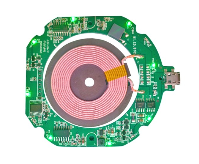
PCB Slip Ring
What Is a PCB Slip Ring?
A PCB Slip Ring is a rotating electrical interface that uses a printed circuit board or PCB-based conductive structure to transmit electrical power and/or signals between stationary and rotating components. Depending on the design, it may include conductive rings, brushes or contacts, insulating materials, bearings, and supporting mechanical structures.
The basic objective is simple: maintain electrical continuity while allowing mechanical rotation. Instead of allowing wires to rotate continuously and eventually become twisted, stressed, or broken, the slip-ring structure provides a controlled electrical path across the rotating interface.
The PCB element can also contribute to circuit routing, miniaturization, mounting convenience, and integration with other electronic assemblies. In my view, this integration is one of the most important reasons engineers should consider this technology. The value is not simply that it can rotate; it is that electrical and mechanical requirements can potentially be addressed within a more compact system architecture.
Key Components of a PCB Slip Ring
A PCB slip ring assembly consists of several crucial parts:
| Component | Function |
|---|---|
| PCB Rotor | Contains circular conductive tracks for signal transmission. |
| Brush Contacts or Spring-loaded Pins | Transfers electrical signals while maintaining a continuous connection. |
| Gold or Silver Plating | Enhances conductivity and reduces wear. |
| Housing and Bearings | Provides mechanical support and rotation stability. |
| Connector Interface | Interfaces with external wiring for seamless integration. |
Types of PCB Slip Rings
PCB slip rings come in different configurations based on application needs and signal transmission requirements.
1. Standard PCB Slip Rings
✔ Designed for compact rotating systems.
✔ Suitable for low-power and low-speed applications.
2. High-Speed PCB Slip Rings
✔ Designed for high-rotation speed (up to 10,000 RPM).
✔ Uses advanced contact materials to minimize wear and resistance.
3. Multi-Channel PCB Slip Rings
✔ Supports multiple independent signal paths (Ethernet, CAN bus, power lines, etc.).
✔ Ideal for robotic arms, radar, and wind turbine applications.
4. Hybrid PCB Slip Rings
✔ Combines power, data, and fiber optic channels in a single compact design.
✔ Used in medical imaging systems and industrial automation.
Advantages of PCB Slip Rings
PCB slip rings offer several benefits over traditional wire-wound slip rings.
1. Compact and Space-Saving Design
✔ Low-profile PCB structure reduces size and weight.
✔ Ideal for miniaturized rotating devices and space-constrained applications.
2. High Signal Transmission Quality
✔ Gold-plated PCB tracks provide low resistance and stable signal transmission.
✔ Suitable for high-speed data transfer (Gigabit Ethernet, USB, HDMI, etc.).
3. Long Lifespan and Low Maintenance
✔ No traditional wire brushes, reducing friction and wear.
✔ Can operate for millions of rotation cycles without failure.
4. High-Speed and Low-Noise Operation
✔ Smooth PCB tracks allow silent operation with minimal signal distortion.
✔ Supports high-RPM applications like aerospace and defense systems.
5. Versatile Signal and Power Transmission
✔ Capable of transmitting DC power, AC signals, digital data, and high-frequency signals.
✔ Supports hybrid configurations for multi-purpose applications.
How Does a PCB Slip Ring Work?
The working principle is based on maintaining electrical contact between rotating and stationary conductive elements. One side of the assembly is connected to the stationary circuit, while the other side rotates with the equipment. Conductive tracks or rings provide the electrical transmission path, while brushes or other contact structures maintain contact during rotation.
When the rotating component turns, the contact point moves continuously along the conductive surface. Electrical power, control signals, sensor signals, or communication signals can therefore pass through the rotating interface without requiring a flexible cable to rotate indefinitely.
Different applications require different contact technologies. Contact materials, surface treatments, contact pressure, ring geometry, insulation, and mechanical tolerances can all influence electrical stability and service life.
Why Does PCB Slip Ring Matter in Modern Electronics?
The increasing demand for compact automation equipment is one reason this technology deserves attention. Many modern devices need multiple functions in a limited mechanical space, while some components must rotate continuously.
For example, robotic joints may require power and signal transmission while rotating. Pan-tilt cameras may need continuous electrical communication without repeatedly winding cables. Medical and laboratory equipment may also require reliable rotating interfaces within relatively compact assemblies.
The important engineering question is therefore not simply whether a slip ring can transmit electricity. Designers should also consider signal integrity, contact resistance, mechanical life, thermal behavior, electromagnetic interference, manufacturability, and maintenance requirements.
A compact design that performs well electrically but suffers from excessive contact wear may not be a successful long-term solution.
PCB Slip Ring Design Considerations
Design begins with the electrical requirements. Engineers need to determine the required number of circuits, voltage, current, signal type, rotational speed, allowable contact resistance, and expected operating life.
Mechanical requirements are equally important. The available installation space, shaft dimensions, bearing arrangement, rotation direction, rotational speed, vibration, and environmental conditions can all affect the final design.
For high-speed or sensitive signal applications, designers should pay particular attention to impedance, parasitic capacitance, electromagnetic interference, and contact stability. High-current applications require additional consideration of conductor width, temperature rise, contact resistance, and heat dissipation.
In my opinion, one common design mistake is treating the PCB only as an electrical routing platform. In a rotating assembly, PCB geometry is closely connected with mechanical reliability. Trace layout, hole locations, clearances, mounting points, and copper distribution can all influence the reliability of the finished structure.
PCB Slip Ring Cost Factors and Performance Impact
The cost of a rotating PCB assembly is influenced by several factors, including PCB material, copper thickness, board dimensions, layer count, number of circuits, contact materials, surface treatment, mechanical tolerances, bearings, assembly complexity, testing requirements, and production volume.
Material selection can have a direct relationship with performance. Standard materials may be sufficient for general-purpose applications, while demanding environments may require materials with better thermal, mechanical, or dimensional stability.
Higher precision also tends to increase manufacturing and inspection costs. Tight tolerances may improve contact stability and mechanical consistency, but they require more sophisticated production processes and quality control.
| Cost Factor | Potential Performance Impact |
|---|---|
| PCB material | Thermal and dimensional stability |
| Copper thickness | Current capacity and heat generation |
| Contact material | Wear resistance and contact reliability |
| Number of circuits | Routing complexity and assembly cost |
| Mechanical tolerance | Rotation smoothness and contact stability |
| Surface treatment | Corrosion resistance and contact performance |
| Testing requirements | Quality assurance and production cost |
| Production volume | Unit cost and process efficiency |
Cost should therefore be evaluated as a system-level consideration rather than simply the purchase price of the PCB. A cheaper component that produces unstable signals, excessive wear, or frequent maintenance can increase the total cost of ownership.
PCB Slip Ring Manufacturing Problems and Solutions
Manufacturing a rotating PCB assembly can introduce several potential problems. Dimensional variation is one concern because small deviations may affect mechanical alignment and contact performance.
Another issue is inconsistent conductive surfaces. Contamination, oxidation, scratches, or inappropriate surface treatment can increase contact resistance and create intermittent electrical connections.
Thermal stress can also become important when relatively high current passes through compact conductive paths. Insufficient copper capacity or poor heat dissipation may lead to excessive temperature rise.
These risks can be reduced through controlled PCB fabrication, appropriate material selection, accurate mechanical assembly, surface-quality inspection, electrical testing, and reliability testing. Designers should also define critical tolerances early instead of waiting until the manufacturing stage to discover that the mechanical and PCB requirements conflict.
PCB Slip Ring Applications
The technology can be used in many rotating electronic systems. Typical applications include robotics, industrial automation, surveillance cameras, rotary sensors, medical equipment, test instruments, antenna systems, and other rotating machinery.
In robotics, a rotating interface can help transmit power and control signals through joints without relying on cables that repeatedly twist. In camera systems, it can support continuous rotation while maintaining electrical connectivity.
For compact sensor systems, the ability to combine electrical transmission with a relatively small mechanical footprint can also be valuable. However, the appropriate structure depends strongly on the application. High-speed data, high current, harsh environments, and high rotational speeds may require substantially different designs.
PCB Slip Ring Reliability and Maintenance
Reliability depends on the interaction between electrical and mechanical factors. Contact wear is a natural concern because repeated rotation can gradually change the contact surfaces.
Dust, moisture, vibration, temperature changes, and chemical exposure can further affect service life. In environments where contamination is likely, sealing and material selection should be considered during the initial design stage.
Electrical testing should include continuity and resistance checks, while mechanical testing may involve rotation endurance, vibration, and temperature testing. For demanding applications, accelerated life testing can provide useful information about potential failure mechanisms before mass production.
Conclusion
A PCB-based slip-ring solution is more than a rotating electrical connector. It is a combination of PCB technology, conductive contact engineering, mechanical rotation, and reliability control.
Its importance comes from a practical engineering challenge: modern equipment increasingly needs to rotate while continuing to transmit power and information in a limited space. When properly designed, a rotating PCB interface can help reduce cable-related problems and support more compact equipment architectures.
At the same time, engineers should not focus only on miniaturization. Contact wear, resistance variation, heat generation, manufacturing tolerance, signal integrity, and environmental conditions can ultimately determine whether the design performs reliably.
Ultimately, the most effective design is not necessarily the smallest or cheapest one. It is the design that achieves an appropriate balance between electrical performance, mechanical reliability, manufacturing capability, service life, and overall system cost.
FAQs
1. What is the main purpose of a PCB Slip Ring?
Its primary purpose is to transmit electrical power or signals between stationary and rotating components while allowing continuous rotation.
2. Where are PCB Slip Rings commonly used?
They can be used in robotics, automation equipment, rotating cameras, sensors, medical equipment, testing systems, and other electromechanical products requiring rotating electrical connections.
3. What factors affect the cost of a PCB Slip Ring?
PCB material, copper thickness, circuit quantity, contact materials, surface treatment, mechanical precision, bearings, assembly complexity, testing requirements, and production volume can all affect cost.
4. What manufacturing problems can occur?
Common problems include dimensional variation, poor conductive-surface quality, excessive contact resistance, contamination, thermal stress, alignment problems, and premature contact wear. Appropriate material selection, process control, inspection, and reliability testing can help reduce these risks.
5. How can engineers improve its reliability?
Engineers should define electrical and mechanical requirements early, select suitable materials and contact structures, control manufacturing tolerances, consider thermal management, protect the assembly from environmental contamination, and conduct electrical and mechanical reliability testing before mass production.

- Special PCB
- long board pcb
- Flexible PCBs
- Special PCB
- Express Printed Circuit Board
- Pcb Prototype
- LED PCB
- PCB
- Pcb Meaning
- Printed Circuit Board
- Pcb manufacturer
- Rigid pcb board
 Quote
 E-mail