Introduction to PCB Power Modules
PCB power modules are specialized circuits designed to manage and distribute electrical power within electronic systems. These modules are critical in applications ranging from consumer electronics to industrial machinery, where efficient power conversion, thermal management, and reliability are paramount. This guide explores the PCB power module processing methods that enable high-performance designs, focusing on material selection, manufacturing techniques, and emerging technologies.
PCB power modules are essential components in modern electronic devices, responsible for efficiently converting, regulating, and distributing electrical power. From consumer electronics to industrial automation, these modules ensure that circuits receive the appropriate voltage and current while minimizing power loss and heat dissipation. As electronic devices become more complex and power demands continue to rise, the need for advanced PCB power module processing methods has grown significantly.
The PCB power module processing method is a critical aspect of modern electronic manufacturing, ensuring the reliability, efficiency, and longevity of power supply units integrated into various devices. Power modules are essential components in everything from consumer electronics to industrial automation, offering stable power conversion and distribution.
The evolution of PCB power module processing methods has been driven by the increasing demand for miniaturized, high-efficiency power solutions. These methods involve a series of design, fabrication, and quality control techniques that enhance performance while minimizing energy loss and thermal issues.
This comprehensive guide delves into the essential PCB power module processing methods, covering everything from materials and design considerations to advanced manufacturing techniques and future trends.
This article explores the critical aspects of PCB power module processing methods, including material selection, design considerations, manufacturing processes, and quality control measures. By understanding these factors, engineers and manufacturers can optimize PCB power module designs for enhanced efficiency, reliability, and performance.
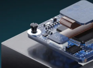
PCB power module
1. Understanding PCB Power Modules
A PCB power module is a self-contained unit that provides regulated power to an electronic circuit. These modules integrate power conversion components such as transformers, capacitors, and semiconductors to efficiently supply voltage and current.
1.1 Functions of PCB Power Modules
-
Voltage Regulation: Ensures a stable output voltage despite input fluctuations.
-
Current Conversion: Converts AC to DC or DC to DC for efficient power supply.
-
Heat Dissipation: Prevents overheating through thermal management strategies.
-
Miniaturization: Reduces circuit complexity by integrating power regulation into a single module.
1.2 Applications of PCB Power Modules
-
Consumer Electronics (smartphones, laptops, gaming consoles)
-
Industrial Automation (motor drives, PLCs, robotics)
-
Automotive Systems (electric vehicles, battery management systems)
-
Medical Devices (portable medical equipment, monitoring devices)
2. Key Components in PCB Power Modules
For efficient PCB power module processing methods, it’s crucial to understand the core components used in these modules:
2.1 Power Semiconductor Devices
-
MOSFETs (Metal-Oxide-Semiconductor Field-Effect Transistors): Ensure efficient switching.
-
IGBTs (Insulated Gate Bipolar Transistors): Used in high-voltage applications.
-
Diodes: Control the direction of current flow and prevent reverse voltage issues.
2.2 Passive Components
-
Capacitors: Filter voltage fluctuations and store energy.
-
Inductors: Reduce noise and manage energy transfer.
-
Resistors: Control current flow and voltage division.
2.3 PCB Substrate Materials
-
FR-4: Standard PCB material offering good insulation.
-
Metal Core PCB (MCPCB): Enhances thermal management.
-
Ceramic PCB: Used in high-power applications for superior heat dissipation.
3. PCB Power Module Processing Method: Design Considerations
Efficient design is the foundation of PCB power module processing methods. The following key design aspects ensure optimal performance:
3.1 Component Placement Strategy
-
Power components should be close to heat dissipation areas.
-
Short and wide traces minimize resistance and voltage drop.
-
High-frequency components should be isolated from noise-sensitive circuits.
3.2 Layer Stack-Up and Copper Thickness
-
Multilayer PCBs enhance power distribution and signal integrity.
-
Thick copper layers (2-4 oz) reduce resistive losses and heat buildup.
3.3 Thermal Management Techniques
-
Thermal Vias: Conduct heat away from power components.
-
Heatsinks & Heat Spreaders: Dissipate excess heat.
-
Metal Core PCBs: Enhance heat transfer in high-power designs.
3.4 EMI and Signal Integrity
-
Ground Planes: Reduce electromagnetic interference (EMI).
-
Shielding Techniques: Minimize noise and crosstalk.
4. PCB Power Module Processing Method: Manufacturing Process
The PCB power module processing method involves multiple steps to ensure precision and reliability.
4.1 PCB Fabrication
-
Design Validation (using EDA software like Altium Designer or KiCad).
-
Etching Process (to define copper traces and power paths).
-
Drilling & Plating (for component mounting and interlayer connections).
4.2 Component Assembly
-
Surface Mount Technology (SMT): For compact power modules.
-
Through-Hole Soldering: For high-current applications.
4.3 Soldering Techniques
-
Reflow Soldering: Melts solder paste to secure SMT components.
-
Wave Soldering: Used for through-hole components.
4.4 Quality Inspection & Testing
-
AOI (Automated Optical Inspection): Detects soldering defects.
-
In-Circuit Testing (ICT): Ensures proper component connectivity.
-
Functional Testing: Verifies power regulation performance.
5. Advanced PCB Power Module Processing Methods
5.1 Embedded Components Technology
-
Integrating passive components within PCB layers for better power distribution.
5.2 High-Density Interconnect (HDI) PCBs
-
Microvias and fine-pitch traces allow for compact power module designs.
5.3 Additive Manufacturing (3D Printing in PCB Fabrication)
-
Conductive ink technology enables flexible PCB power modules.
6. Challenges in PCB Power Module Processing Methods
6.1 Miniaturization vs. Heat Dissipation
-
Shrinking power modules increases thermal stress, requiring innovative cooling solutions.
6.2 Manufacturing Defects
-
Soldering Defects (cold solder joints, bridges).
-
Material Defects (delamination, warpage).
6.3 Power Integrity Issues
-
Improper layout can cause voltage drops and signal distortions.
7. Future Trends in PCB Power Module Processing Methods
7.1 Gallium Nitride (GaN) and Silicon Carbide (SiC) Power Modules
-
Next-gen power semiconductors offer higher efficiency and faster switching speeds.
7.2 AI and Automation in PCB Manufacturing
-
Machine learning optimizes component placement and defect detection.
7.3 Eco-Friendly PCB Power Module Processing Methods
-
Lead-free soldering and biodegradable substrates reduce environmental impact.
2. Importance of PCB Power Module Processing Method
PCB power modules play a vital role in ensuring the stability and functionality of electronic systems. The quality of the PCB power module processing method directly impacts the efficiency, durability, and operational reliability of the final product. Here are some key reasons why advanced processing methods are crucial:
-
Power Efficiency: Efficient power conversion reduces energy loss, improving the overall performance of the device.
-
Thermal Management: Advanced processing techniques help dissipate heat effectively, preventing component failure due to overheating.
-
Miniaturization: Modern devices demand compact power modules, requiring precise manufacturing methods to accommodate smaller form factors.
-
Reliability & Longevity: High-quality materials and processing techniques enhance the durability of PCB power modules, reducing failure rates and maintenance costs.
By implementing optimized PCB power module processing methods, manufacturers can ensure high-quality power modules that meet stringent industry standards and customer expectations.
3. Key Components of a PCB Power Module
Before diving into the specific PCB power module processing methods, it’s essential to understand the fundamental components that make up a power module:
-
Power Semiconductor Devices: These include MOSFETs, IGBTs, and diodes, which are responsible for switching and regulating power.
-
Inductors & Transformers: Used for energy storage and voltage conversion, ensuring stable power delivery.
-
Capacitors: Essential for filtering and stabilizing voltage levels in power circuits.
-
PCB Substrate: Provides structural support and electrical connections for components while offering thermal management properties.
-
Connectors & Terminals: Facilitate input and output connections for power transmission.
Each of these components must be carefully selected and processed to ensure optimal performance in PCB power modules.
4. Material Selection for PCB Power Module Processing
Choosing the right materials is crucial for PCB power module processing methods, as it directly affects electrical conductivity, heat dissipation, and durability. The most commonly used materials include:
-
PCB Substrate Materials:
-
FR-4: Standard material offering good insulation and moderate thermal conductivity.
-
Metal Core PCB (MCPCB): Ideal for power modules requiring enhanced heat dissipation.
-
Ceramic PCBs: Used for high-power applications due to their superior thermal management capabilities.
-
-
Conductive Traces & Layers:
-
Copper: The most widely used conductor due to its excellent electrical and thermal conductivity.
-
Gold or Silver Plating: Improves oxidation resistance and enhances solderability.
-
-
Thermal Interface Materials (TIMs):
-
Thermal Grease: Helps transfer heat from power components to heatsinks.
-
Thermally Conductive Adhesives: Secure components while improving heat dissipation.
-
Proper material selection ensures that PCB power module processing methods produce reliable and high-performance modules.
5. Design Considerations for PCB Power Modules
The design phase is critical in optimizing PCB power module processing methods. Engineers must carefully plan the PCB layout to maximize efficiency, reduce interference, and ensure effective thermal management. Key design factors include:
-
Component Placement
-
High-power components should be positioned near heat sinks or thermal vias for better heat dissipation.
-
Signal traces should be kept short to minimize resistance and power loss.
-
-
Layer Stackup & Copper Thickness
-
Multilayer PCBs improve signal integrity and power distribution.
-
Copper thickness should be selected based on current-carrying capacity requirements.
-
-
Thermal Management Strategies
-
Incorporating thermal vias to conduct heat away from critical areas.
-
Using metal-backed PCBs for improved heat dissipation in high-power applications.
-
-
Electromagnetic Interference (EMI) Reduction
-
Shielding techniques such as ground planes and EMI filters should be included in the design.
-
Proper spacing between power and signal traces helps minimize crosstalk.
-
By implementing these best practices, manufacturers can enhance the efficiency and reliability of PCB power modules.
6. Manufacturing Techniques for PCB Power Modules
The manufacturing process plays a crucial role in ensuring that PCB power module processing methods produce high-quality products. The key steps involved include:
-
PCB Fabrication
-
The base PCB is manufactured using advanced fabrication techniques, including etching, drilling, and plating.
-
High-precision methods such as laser drilling ensure accurate hole placement for power components.
-
-
Component Assembly
-
Surface Mount Technology (SMT) is commonly used for compact power module designs.
-
Through-hole soldering may be employed for components requiring strong mechanical connections.
-
-
Soldering Processes
-
Reflow Soldering: Used for SMT components, ensuring reliable connections.
-
Wave Soldering: Suitable for through-hole components, providing strong and uniform solder joints.
-
-
Testing & Quality Control
-
Automated Optical Inspection (AOI) detects defects in solder joints and component placement.
-
Electrical Testing verifies that the power module functions correctly under various load conditions.
-
Implementing PCB power module processing methods with stringent quality control measures ensures defect-free and reliable power modules.
6. Thermal Management in PCB Power Modules
Heat Sink Integration
- Bonded Heatsinks: Attach aluminum/copper heatsinks to PCB surfaces using thermal adhesives.
- Liquid Cooling Channels: Microfluidic channels etched into metal-core PCBs for active cooling.
Thermal Interface Materials (TIMs)
- Thermal Pads and Greases: Enhance heat transfer between components and heatsinks.
- Phase-Change Materials (PCMs): Absorb and dissipate heat during transient loads.
7. Testing and Validation of PCB Power Modules
Electrical Performance Testing
- Efficiency Measurement: Input/output power analysis under load conditions.
- Transient Response Testing: Evaluate stability during rapid load changes.
Thermal Cycling and Reliability
- Temperature Shock Tests: Expose modules to -40°C ↔ +125°C cycles (per MIL-STD-883).
- Vibration Testing: Validate mechanical robustness in automotive/aerospace environments.
EMI/EMC Compliance
- Radiated Emissions Testing: Ensure compliance with FCC Part 15 or CISPR 32.
- Surge and ESD Immunity: Protect against transient voltages (IEC 61000-4-5).
8. Case Studies: PCB Power Module Applications
Case 1: Electric Vehicle (EV) Onboard Charger
- Challenge: High power density (≥10 kW/L) with thermal stability.
- Solution: Hybrid MCPCB with embedded GaN FETs and liquid cooling.
Case 2: Industrial Motor Drive
- Challenge: Mitigate EMI from PWM-controlled IGBTs.
- Solution: Shielded power modules with partitioned ground planes.
Case 3: Renewable Energy Inverter
- Challenge: Long-term reliability in outdoor environments.
- Solution: Conformal-coated PCBs with ceramic-filled substrates.
9. Challenges in PCB Power Module Processing
Material Compatibility Issues
- CTE Mismatch: Differential expansion between copper and substrates causes warping.
- Solution: Low-CTE laminates (e.g., polyimide) or flexible adhesives.
High-Cost Advanced Materials
- Ceramic Substrates: High performance but expensive.
- Mitigation: Optimize designs to minimize substrate area.
Manufacturing Defects
- Delamination: Poor adhesion between layers under thermal stress.
- Prevention: Strict humidity control during lamination.
10. Innovations in PCB Power Module Processing Methods
Wide Bandgap (WBG) Semiconductor Integration
- Silicon Carbide (SiC) and Gallium Nitride (GaN): Enable higher efficiency and switching frequencies.
- Embedded WBG Devices: Direct mounting onto DPC substrates.
AI-Driven Design Optimization
- Generative Algorithms: Auto-generate layouts for minimal losses and thermal hotspots.
- Digital Twins: Simulate thermal and electrical performance pre-production.
Sustainable Manufacturing Practices
- Lead-Free Soldering: Comply with RoHS directives.
- Recyclable Materials: Bio-based laminates and halogen-free prepregs.
11. Future Trends in PCB Power Modules
Ultra-High-Density Power Modules
- 3D Packaging: Stacked dies and vertical interconnects for compact designs.
- Nanoscale Cooling: Carbon nanotube-based thermal interfaces.
Wireless Power Integration
- Inductive Charging Circuits: PCB coils for contactless energy transfer.
- Resonant Wireless Systems: High-efficiency modules for IoT devices.
Smart Power Modules
- Integrated Sensors: Real-time monitoring of temperature, current, and voltage.
- Edge AI Controllers: On-board diagnostics for predictive maintenance.
Conclusion
The PCB power module processing method is a crucial aspect of modern electronic design and manufacturing. By selecting the right materials, optimizing PCB layouts, implementing advanced manufacturing techniques, and ensuring rigorous testing, engineers can develop high-performance power modules for various applications.
With the advancement of GaN technology, AI-driven design optimization, and sustainable manufacturing methods, the future of PCB power module processing methods is set to bring higher efficiency, reduced form factors, and better reliability.
By staying ahead of emerging trends and adopting innovative PCB power module processing methods, manufacturers can enhance their competitiveness in the rapidly evolving electronics industry.

- long board pcb
- Flexible PCBs
- Special PCB
- Express Printed Circuit Board
- Pcb Prototype
- LED PCB
- PCB
- Printed Circuit Board
- Pcb meaning
- Pcb manufacturer
- Rigid pcb board
- Rigid Flex PCB
 Quote
Quote
 E-mail