Introduction
In PCB (Printed Circuit Board) manufacturing, drilling is one of the most high-speed and precision-intensive processes. Modern mechanical and laser drilling machines operate at staggering speeds, ensuring efficient and precise hole creation for vias, through-holes, and microvias. With spindle speeds reaching hundreds of thousands of RPM and drilling rates exceeding 100,000 holes per minute, today’s PCB drilling technology has set new benchmarks in efficiency and accuracy.
For this reason, PCB Drilling Speed deserves more attention than simply asking how fast a drilling machine can operate. Spindle speed, feed rate, drill diameter, material structure, tool wear, and chip evacuation must work together. Research and industry guidance show that inappropriate combinations of rotational speed and feed can contribute to burrs, resin smear, rough hole walls, nail heading, tool wear, and positional errors.
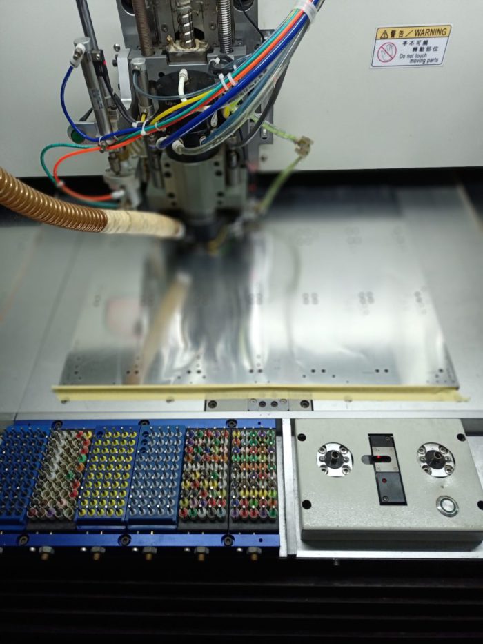
PCB Drilling Speed
PCB Drilling Speed: What Does It Actually Mean?
PCB Drilling Speed refers broadly to the operating speed of a PCB drilling process, but it is important to distinguish between several related parameters. Spindle speed is normally expressed in revolutions per minute (RPM) and describes how quickly the drill rotates. Feed rate describes how quickly the drill advances into the PCB material, while drilling rate can also refer to the number of holes processed over a given period.
These parameters are closely connected through chip load—the amount of material removed by each cutting edge during each revolution. Increasing RPM without appropriately controlling feed rate can create excessive heat or unfavorable cutting conditions. Conversely, excessive feed at an unsuitable spindle speed can increase mechanical stress, burr formation, drill deflection, and tool breakage.
The correct target, therefore, is not maximum speed. It is stable and repeatable drilling performance. For example, very small mechanical drills may require extremely high spindle speeds because their small diameter otherwise produces insufficient cutting speed at the tool edge. IPC technical material has documented mechanical microdrilling at spindle speeds around 300,000 RPM and linked appropriate cutting speed with drill life and hole quality.
PCB Drilling Speed: Why Does It Need More Attention?
One reason is the increasing density of modern PCBs. HDI boards, fine-pitch packages, high-layer-count boards, and compact electronic products require smaller holes and tighter positional tolerances. A small deviation during drilling can subsequently affect copper plating, via connection, soldering, and electrical reliability.
Another reason is that drilling involves multiple materials. A conventional multilayer PCB may contain copper foil, resin, and glass-fiber reinforcement, each responding differently to the cutting process. Research has shown that spindle speed, feed rate, and tool wear can influence hole-wall roughness, burr formation, nail heading, and other hole-quality characteristics.
My view is that manufacturers should treat drilling speed as a process-control issue rather than a machine-speed specification. A faster machine does not automatically produce a better PCB. The real competitive advantage comes from finding a stable parameter window that balances productivity, tool life, dimensional accuracy, and downstream reliability.
PCB Drilling Speed: Cost Factors Manufacturers Should Consider
The economic impact of drilling is broader than machine cycle time. A higher production rate can reduce labor and equipment time per panel, but excessive speed can increase tool wear, breakage, rework, and scrap.
| Cost Factor | Potential Impact |
|---|---|
| Spindle speed | Affects productivity, heat generation, and tool behavior |
| Feed rate | Influences cycle time, cutting load, burrs, and hole quality |
| Drill-bit consumption | Worn or broken tools increase consumable costs |
| Material stack-up | Difficult materials may require more conservative parameters |
| Machine maintenance | Spindle accuracy and runout influence drilling consistency |
| Rework and scrap | Poor holes can increase downstream manufacturing costs |
| Inspection | High-density boards may require additional quality verification |
Tool wear is particularly important for small-diameter drilling. Studies have found that micro-drill wear can increase cutting forces and negatively affect hole-wall quality and hole-location accuracy.
Therefore, the cheapest drilling process is not necessarily the process with the highest nominal drilling rate. A slightly more conservative parameter that extends tool life and reduces defective panels can produce a lower total manufacturing cost.
PCB Drilling Speed: How Does It Affect PCB Performance?
The drilling process creates the physical foundation for many electrical connections on a PCB. Hole diameter, position, wall condition, burr formation, and subsequent copper plating all influence the final interconnection.
If drilling parameters are poorly controlled, several problems may occur:
- Resin smear: Heat and unsuitable cutting conditions can soften resin and contaminate hole walls.
- Burr formation: Excessive feed or unstable cutting conditions can leave unwanted material around hole entrances or exits.
- Nail heading: Copper deformation may occur around drilled holes.
- Hole-wall roughness: Excessive tool wear or inappropriate parameters can deteriorate the hole surface.
- Drill wander: Small drills can deflect, resulting in positional inaccuracies.
- Drill breakage: Excessive mechanical loading can damage fragile small-diameter tools.
- Delamination: Excessive mechanical or thermal stress can damage the laminate structure.
These defects are not merely cosmetic. Poor hole quality can complicate desmear and copper plating and may ultimately affect via reliability and electrical continuity.
PCB Drilling Speed: Common Production Problems and Solutions
A practical drilling strategy should begin with the complete stack-up rather than an isolated RPM number. Drill diameter, PCB thickness, copper thickness, laminate type, aspect ratio, entry material, backup material, and tool condition should all be considered.
| Production Problem | Possible Cause | Practical Solution |
|---|---|---|
| Excessive burrs | Feed too aggressive, worn drill | Optimize feed and replace worn tools |
| Resin smear | Excessive heat or unsuitable cutting conditions | Adjust RPM/feed and improve chip evacuation |
| Drill breakage | Excessive load, runout, or tool wear | Reduce mechanical stress and check spindle condition |
| Hole-position error | Drill deflection or spindle runout | Check tooling, registration, and spindle accuracy |
| Rough hole walls | Tool wear or unstable cutting | Monitor tool life and optimize parameters |
| Delamination | Excessive mechanical/thermal stress | Optimize drilling conditions and stack support |
High spindle speed can be beneficial, particularly for microdrilling, but it should not be treated as an independent variable. Extremely high rotational speed can also introduce issues such as spindle or chuck imbalance and radial runout, which may negatively affect hole accuracy and wall quality.
The better approach is to establish validated drilling windows for different drill diameters and materials, then continuously monitor actual production performance.
PCB Drilling Speed: How Manufacturers Can Optimize the Process
A reliable optimization process normally follows several steps. First, select the appropriate drill geometry and diameter for the hole design. Second, determine a suitable spindle-speed range based on tool diameter and PCB material. Third, establish feed rate through chip-load considerations rather than simply increasing feed to shorten cycle time.
Machine condition should also be monitored. Spindle runout, collet condition, drill alignment, entry and backup materials, and panel stability can all influence drilling results.
Finally, manufacturers should track measurable indicators such as hole diameter, positional accuracy, burr height, hole-wall condition, drill wear, and breakage frequency. This converts drilling from a machine-setting exercise into a measurable manufacturing-control process.
For customers purchasing precision PCBs, this distinction is important. A supplier that can demonstrate stable drilling parameters, tool-life management, and inspection procedures is better positioned to maintain consistency across repeated production batches.
PCB Drilling Speed: The Right Balance Between Speed and Precision
High-speed PCB production requires a balance between productivity and quality. Increasing spindle RPM may reduce cutting forces for certain small-diameter applications, but feed rate, chip load, tool geometry, and machine stability must remain compatible with that speed. Published studies and technical guidance consistently indicate that drilling parameters influence both productivity and hole quality.
In my opinion, this is the most important point for PCB manufacturers: speed should be optimized for the finished hole, not for the machine display. A drilling machine running at an impressive RPM is meaningless if the resulting holes require rework or create reliability problems later in plating and assembly.
For high-density and high-reliability PCBs, process stability is ultimately more valuable than simply maximizing drilling throughput.
PCB Drilling Speed: Conclusion
As PCB designs continue to move toward higher density, smaller geometries, thinner structures, and more complex multilayer configurations, drilling has become one of the manufacturing processes that cannot be treated simply as a matter of machine productivity. The quality and consistency of drilled holes directly influence subsequent desmear, copper plating, via formation, soldering, and ultimately the electrical and mechanical reliability of the finished PCB. For this reason, controlling drilling parameters is an important part of building a stable and repeatable PCB manufacturing process.
Spindle speed and feed rate are at the center of drilling optimization, but neither parameter should be considered independently. The appropriate combination depends on drill diameter, laminate composition, copper thickness, board thickness, stack-up configuration, tool geometry, machine capability, and expected hole quality. A parameter that performs well on a conventional FR-4 board may not necessarily produce the same results on an HDI board, high-Tg laminate, thick-copper PCB, or other specialized construction.
From a manufacturing perspective, the objective should not simply be to achieve the highest possible drilling rate. Excessive speed or an unsuitable feed rate can increase heat generation, tool wear, burr formation, resin smear, drill breakage, and positional errors. These problems can create additional costs through tool consumption, rework, inspection, rejected panels, and downstream plating defects. In contrast, a properly controlled drilling process can improve productivity while maintaining hole accuracy and reducing unnecessary manufacturing losses.
Another important consideration is tool-life management. As a drill becomes worn, cutting conditions change and hole quality can gradually deteriorate. Manufacturers therefore need to monitor tool usage and establish appropriate replacement criteria instead of waiting until a visible drilling defect occurs. Spindle runout, collet condition, machine vibration, panel support, and chip evacuation should also be included in routine process control because even well-designed drilling parameters cannot compensate for an unstable mechanical system.
For customers evaluating PCB suppliers, this also provides a useful perspective. A supplier’s drilling capability should not be judged only by the maximum spindle RPM or advertised production capacity. More meaningful indicators include the supplier’s ability to maintain consistent hole diameter, positional accuracy, hole-wall quality, tool-life control, and production stability across repeated batches. These capabilities become particularly important when manufacturing HDI, fine-pitch, high-layer-count, or high-reliability PCBs where even relatively small drilling variations can have downstream consequences.
In my view, the real value of high-speed drilling is not simply drilling more holes in less time. It is achieving a carefully controlled balance between speed, accuracy, tool life, material behavior, and manufacturing yield. When these factors are optimized together, manufacturers can shorten production cycles without sacrificing the quality required by increasingly demanding electronic applications.
Ultimately, effective drilling is a combination of engineering knowledge, equipment capability, process control, and continuous monitoring. As PCB technology continues to evolve, manufacturers that approach drilling as a precision process rather than merely a high-speed operation will be better positioned to maintain consistent quality, control production costs, and meet the increasingly strict requirements of modern electronics. For high-density and precision PCB manufacturing, the goal should always be the same: the right speed, the right tool, the right process window, and a consistently reliable hole.
1. What is PCB Drilling Speed?
It generally describes the operating speed of PCB drilling, including spindle RPM, feed rate, and sometimes the number of holes processed per unit of time. These parameters work together to determine drilling productivity and hole quality.
2. Does Higher PCB Drilling Speed Always Improve Quality?
No. Higher spindle speed can be beneficial for certain small-diameter drills, but excessive or poorly matched speed can increase heat, runout, or tool wear. The correct parameters depend on drill diameter, material, feed rate, and machine conditions.
3. How Does Feed Rate Affect PCB Drilling?
Feed rate determines how quickly the drill moves into the PCB. If it is too high, mechanical loading, burrs, and hole damage may increase. If it is too low for the selected RPM, the drill may rub instead of cutting efficiently, generating unnecessary heat and wear.
4. What Problems Can Incorrect Drilling Parameters Cause?
Common problems include burrs, resin smear, nail heading, rough hole walls, drill breakage, hole-position errors, and delamination. These defects can subsequently complicate plating and reduce interconnection reliability.
5. How Can PCB Manufacturers Optimize Drilling Performance?
Manufacturers should optimize spindle speed and feed rate together, select appropriate tools, control drill life, maintain spindle accuracy, stabilize the PCB stack, and inspect hole quality during production. Parameter validation on the actual PCB material and stack-up is more reliable than simply copying generic machine settings.

- Special PCB
- long board pcb
- Flexible PCBs
- Special PCB
- Express Printed Circuit Board
- Pcb Prototype
- LED PCB
- PCB
- Pcb Meaning
- Printed Circuit Board
- Pcb manufacturer
- Rigid pcb board
 Quote
 E-mail