How to Connect Two PCB Boards: A Complete Guide for Engineers
Connecting two printed circuit boards (PCBs) is a common task in the design and manufacturing of complex electronic systems. Whether you’re designing a multi-layer system, an interconnected device, or a modular assembly, connecting PCBs effectively ensures the proper flow of signals and power between different components. This guide will explore various methods to connect two PCBs, the considerations for choosing the right method, and best practices to ensure reliable and efficient connections.
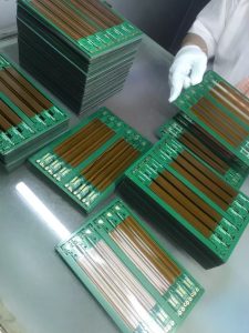
how to connect two pcb boards
Understanding PCB Connections
PCBs are essential for interconnecting electrical components and creating circuits within electronic systems. As devices become more complex, it’s often necessary to connect two or more PCBs to create a more efficient design. The process of connecting PCBs ensures that the components on each board can communicate and work together seamlessly.
The connection of PCBs depends on several factors, including the form factor, the number of signal and power lines to be transmitted, the space available, and the type of components used. Engineers need to select the best method based on the specific requirements of their design, the environment in which the device will operate, and the signal integrity needed.
Types of PCB Connections
There are several methods available for connecting two PCBs, each suited to different types of applications. The choice of connection method depends on the mechanical, electrical, and thermal requirements of the system. Below are the most common methods used for connecting PCBs.
How to connect two pcb boards
1. Flexible Printed Circuit (FPC) Cables
Flexible printed circuits (FPCs) are a popular choice for connecting two PCBs, especially when the boards are not aligned in a single plane or when they need to be connected in a compact, flexible design. FPCs consist of flexible, thin circuit materials that allow for easy routing of electrical signals between the two PCBs.
FPC cables are particularly useful when the PCBs need to be connected in a limited space or require flexibility, such as in mobile devices, wearable electronics, or automotive applications. The primary advantage of FPCs is their flexibility and the ability to connect components on different planes without requiring bulky connectors.
Advantages of FPC:
- Flexibility and space-saving
- Lightweight design
- Excellent for small, portable electronics
- Suitable for connecting non-aligned PCBs
Disadvantages of FPC:
- Limited durability, especially in environments with high mechanical stress
- Can be difficult to manufacture in large quantities
2. Board-to-Board (B2B) Connectors
Board-to-board (B2B) connectors are another common method for connecting two PCBs. These connectors create a direct electrical connection between the two boards using pins or sockets. B2B connectors come in different sizes, types, and configurations, such as:
-
Pin Header and Socket Connectors: These connectors are used for connecting two PCBs with male and female pins. Pin headers are mounted on one PCB, and the corresponding sockets are mounted on the other PCB. The two PCBs can be easily connected or disconnected without soldering.
-
Stacked Connectors: These are used when the two PCBs are stacked on top of each other. The connectors have male pins on one board that insert into female sockets on the other board, allowing a secure connection.
Advantages of B2B Connectors:
- Easy to assemble and disassemble
- Widely used and available in various sizes and configurations
- Strong electrical and mechanical connection
- Ideal for high-density designs
Disadvantages of B2B Connectors:
- Requires precise alignment of the boards
- Can be bulky in certain designs
- Can be expensive depending on the type of connector
3. Wire-to-Board Connections
Wire-to-board connections involve connecting the two PCBs through wires that are soldered onto the boards. This method is often used in situations where a direct connection through connectors is not practical, or when space is limited. The wires are typically attached to the PCB through vias or pin headers and then routed to the other board.
This method is particularly useful when connecting components that require specific routing, or when the boards need to be positioned at a distance from one another. Wire-to-board connections are common in designs where the two PCBs are not stacked or aligned in a single plane.
Advantages of Wire-to-Board:
- Flexible routing options
- Suitable for situations where other connection methods may be impractical
- Low cost and easy to implement
Disadvantages of Wire-to-Board:
- Less reliable than other connection methods
- Increased risk of wiring errors or shorts
- Requires careful routing and organization of the wires
4. Solder Bridges (Direct Soldering)
For a more permanent connection between two PCBs, direct soldering or solder bridges can be used. In this method, wires or pads on each PCB are directly soldered to one another to establish an electrical connection. This method is commonly used in prototype designs or when a very stable and durable connection is required.
Direct soldering is ideal for applications where the boards will not need to be disconnected regularly and where long-term durability and reliability are important. However, this method is not suitable for designs that require disassembly or reconfiguration.
Advantages of Solder Bridges:
- Highly reliable and secure connection
- Low cost if used in small quantities
- No need for additional components (such as connectors)
Disadvantages of Solder Bridges:
- Permanent connection (not suitable for reconfiguration or repair)
- Requires skilled labor for proper soldering
- Not suitable for large-scale or mass production designs
5. Ribbon Cables
Ribbon cables are a type of flat, multi-conductor cable that can be used to connect two PCBs. These cables have multiple conductors arranged in parallel, making it easy to transmit multiple signals between the two boards. Ribbon cables are often used in applications where a large number of connections are needed in a compact form factor.
Ribbon cables can be terminated with connectors or directly soldered to the PCB, depending on the application. These cables are commonly used in industrial machinery, computer systems, and consumer electronics.
Advantages of Ribbon Cables:
- Compact and organized wiring for multiple connections
- Easy to manufacture and assemble
- Suitable for applications requiring many connections
Disadvantages of Ribbon Cables:
- Limited flexibility compared to other methods like FPC
- Can be bulky in certain designs
Factors to Consider When Choosing a Connection Method
When deciding how to connect two PCBs, engineers must take several factors into account to ensure the best performance and reliability for the application. Some of the key factors include:
1. Space Constraints
The available space between the two PCBs is one of the most critical considerations. In tight spaces, flexible connections like FPC or ribbon cables may be the best choice, as they allow for compact and flexible designs.
2. Signal Integrity
For applications where signal integrity is critical, such as high-speed digital circuits or analog signals, engineers must choose connection methods that minimize signal degradation or interference. In these cases, direct soldering or using high-quality B2B connectors with proper shielding may be more appropriate.
3. Mechanical Stress and Durability
For applications that will experience mechanical stress, vibration, or harsh environments, it is important to select a connection method that can withstand these conditions. B2B connectors, ribbon cables, or direct soldering may be more reliable in such situations.
4. Ease of Assembly
Some connection methods, such as wire-to-board or B2B connectors, may be easier to assemble and modify, especially in prototyping or small-scale production runs. In contrast, direct soldering is a more permanent and stable option but may require more expertise.
5. Cost and Manufacturing Complexity
The chosen connection method will also impact the overall cost of production. For large-scale manufacturing, methods that use pre-fabricated connectors or ribbon cables may be more cost-effective. However, for small runs or prototyping, solder bridges or direct soldering can be more economical.
Conclusion
Connecting two PCBs effectively is an essential aspect of designing complex electronic systems. The choice of connection method depends on several factors, including the application, available space, signal integrity requirements, mechanical stresses, and cost. Whether using flexible FPC cables, reliable board-to-board connectors, or direct soldering, understanding the pros and cons of each method ensures that engineers can select the most suitable connection strategy for their specific needs. By considering the key factors and best practices, designers can achieve optimal performance, reliability, and cost-efficiency in their PCB designs.

- long board pcb
- Flexible PCBs
- Special PCB
- Express Printed Circuit Board
- Pcb Prototype
- LED PCB
- PCB
- Printed Circuit Board
- Pcb meaning
- Pcb manufacturer
- Rigid pcb board
- Rigid Flex PCB
 Quote
Quote
 E-mail