Functional Verification Testing (FVT Test) in PCB Manufacturing: Methods, Parameters, and Best Practices
1. Introduction to FVT Testing
Functional Verification Testing (FVT test) is a critical step in PCB (Printed Circuit Board) manufacturing and electronic assembly. It ensures that a fully assembled PCB functions correctly under real-world operating conditions. Unlike basic electrical tests that check continuity and isolation, FVT focuses on verifying circuit functionality, performance, and reliability before deployment.
FVT testing plays an essential role in high-reliability industries, including automotive, aerospace, telecommunications, medical devices, and consumer electronics. A well-executed FVT process helps manufacturers reduce defects, improve product quality, and minimize failure rates in the field.
This article provides a comprehensive guide on FVT testing, its purpose, testing methods, key parameters, and best practices for ensuring high-performance PCB assemblies.
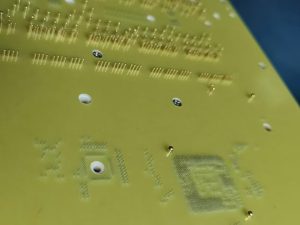
FVT Test
2. What is FVT Testing?
Functional Verification Testing (FVT test) is a final-stage PCB test performed on a fully assembled and operational board to check if it meets design specifications and performance requirements.
Unlike ICT (In-Circuit Testing) or AOI (Automated Optical Inspection), which focus on component placement and solder joint quality, FVT ensures that the PCB behaves as expected under real-world conditions.
2.1 Purpose of FVT Testing
✅ Detect Functional Defects: Identifies faults such as incorrect voltage levels, communication failures, and timing errors.
✅ Validate Circuit Performance: Ensures the PCB meets design specifications and operational requirements.
✅ Verify Firmware and Software Integration: Confirms that embedded software and firmware function correctly with hardware.
✅ Improve Product Reliability: Reduces failure rates by testing under realistic environmental conditions.
2.2 When is FVT Testing Performed?
FVT testing is usually conducted after PCB assembly (PCBA) and before final product integration. It is commonly used in:
Prototype testing – Ensures early-stage validation before mass production.
Production testing – Performed on a sample batch or every unit in high-reliability applications.
End-of-line testing – A final quality control step before shipping the product.
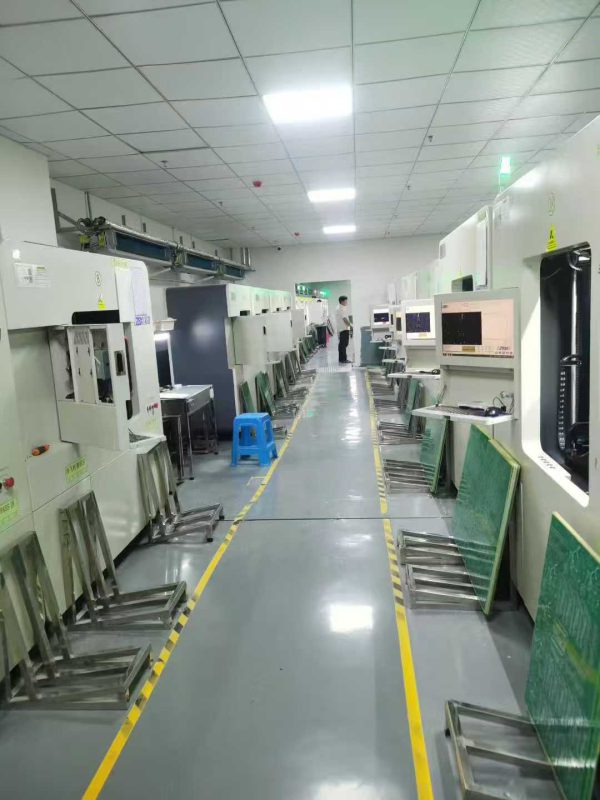
Flying Probe Test
3. Key Methods of FVT Testing
Different testing methods are used in FVT, depending on the complexity of the PCB, functionality, and industry requirements.
3.1 Manual Testing
Engineers manually probe and measure signals using oscilloscopes, multimeters, and function generators.
Used for low-volume production, prototypes, and troubleshooting.
Time-consuming and dependent on human accuracy.
3.2 Automated Functional Testing (AFT)
Uses automated test systems (ATEs) to apply power and execute predefined test scripts.
Suitable for high-volume production to ensure consistency and reliability.
Provides detailed pass/fail reports and logs for quality analysis.
3.3 In-System Testing (IST)
Verifies PCB functionality after firmware or software has been programmed.
Ensures communication interfaces (USB, UART, SPI, I2C, etc.) are functional.
Validates microcontroller, FPGA, or embedded system integration.
3.4 Stress Testing & Environmental Simulation
Evaluates performance under extreme conditions such as temperature, humidity, and vibration.
Used for automotive, aerospace, and industrial applications.
Identifies potential failure points in harsh environments.
3.5 Boundary Scan Testing (JTAG Testing)
Uses the JTAG (Joint Test Action Group) interface to verify connectivity and functionality.
Ideal for complex, high-density PCBs with limited test access.
Checks for faulty solder joints, missing components, and internal logic errors.
4. Key Parameters Tested in FVT
During an FVT test, various electrical and functional parameters are verified to ensure compliance with design specifications.
4.1 Power Supply & Voltage Regulation
✅ Verifies input voltage, power rails, and current consumption.
✅ Checks for voltage drops, spikes, or unstable power regulation.
4.2 Signal Integrity & Communication Interfaces
✅ Ensures proper functionality of USB, Ethernet, SPI, I2C, CAN, UART, and other interfaces.
✅ Tests clock signals, data transmission speed, and error rates.
4.3 Analog & Digital Circuit Testing
✅ Measures amplifier gain, ADC/DAC performance, and sensor responses.
✅ Validates switching circuits, logic gates, and microcontroller functions.
4.4 Timing & Frequency Response
✅ Verifies oscillator frequency, clock synchronization, and signal timing delays.
✅ Ensures proper operation of PWM (Pulse Width Modulation) signals.
4.5 Thermal Performance & Power Dissipation
✅ Monitors PCB temperature rise under load conditions.
✅ Identifies potential overheating risks in power electronics and high-current circuits.
5. Challenges in FVT Testing
5.1 Complex PCB Designs
High-density PCBs have limited test access, making manual probing difficult.
Solution: Use JTAG boundary scan or automated test fixtures.
5.2 Firmware & Software Bugs
Embedded firmware issues can cause unexpected failures during testing.
Solution: Implement automated software verification before FVT.
5.3 Inconsistent Test Results
Variability in test setups can lead to inaccurate measurements.
Solution: Use standardized test procedures and fixtures.
5.4 Environmental Variability
Temperature, humidity, and external noise can affect test outcomes.
Solution: Conduct tests in controlled environments with proper shielding.
6. Best Practices for Effective FVT Testing
To ensure a successful FVT test process, follow these best practices:
✅ Design for Testability (DFT): Include test points, JTAG connectors, and debug interfaces during PCB design.
✅ Automate Testing Where Possible: Reduces human error and increases test efficiency.
✅ Use Standardized Test Scripts: Ensures repeatability and consistency across multiple test runs.
✅ Monitor and Log Test Data: Helps in quality analysis, failure tracking, and product improvement.
✅ Collaborate with PCB Manufacturers: Work with high-quality PCB providers to minimize fabrication-related defects.
7. Future Trends in FVT Testing
With advancements in AI-driven automation and machine learning, FVT testing is evolving to provide faster, more accurate, and scalable solutions. Key trends include:
🔹 AI-Powered Test Systems: Machine learning algorithms optimize test procedures.
🔹 IoT-Based Remote Testing: Cloud-based platforms enable real-time monitoring and diagnostics.
🔹 Automated Optical & X-Ray Inspection (AXI): Combines functional and structural testing for higher defect detection rates.
🔹 5G & High-Speed Signal Testing: New standards for ultra-fast data transmission validation.
These innovations will continue to enhance PCB testing efficiency, reduce costs, and improve product reliability.
8. Conclusion: Ensuring PCB Reliability with FVT Testing
Functional Verification Testing (FVT test) is a critical quality control step in PCB manufacturing. By performing comprehensive functional tests, power integrity checks, signal analysis, and environmental simulations, manufacturers can prevent failures, reduce returns, and improve product performance.
For high-quality PCB fabrication and testing, Shenzhen Shuoqiang Electronics offers advanced FVT solutions to ensure your circuit boards meet the highest reliability standards.
FAQs: Functional Verification Testing (FVT) in PCB Manufacturing
Q1: What is the difference between FVT and ICT testing?
A: ICT (In-Circuit Testing) checks for assembly defects such as open circuits, shorts, or incorrect component values, while FVT (Functional Verification Testing) ensures the fully assembled PCB operates according to design specifications under real-world conditions.
Q2: Is FVT testing necessary for every PCB?
A: Not always. For consumer-grade or low-cost electronics, sample-based FVT may be sufficient. However, in industries like automotive, aerospace, or medical devices, 100% FVT is critical to guarantee reliability and safety.
Q3: How long does an FVT test usually take?
A: The duration depends on PCB complexity and the number of parameters tested. Simple boards may take a few minutes, while complex, multi-layer boards with embedded software can require 30 minutes or more per unit.
Q4: Can FVT testing detect software-related issues?
A: Yes. Unlike ICT or AOI, FVT also validates firmware and software integration, ensuring that embedded programs work correctly with the hardware. This makes it essential for microcontroller- or FPGA-based systems.
Q5: How can manufacturers reduce the cost of FVT testing?
A: Costs can be reduced by designing for testability (DFT), automating test setups, using standardized test scripts, and implementing boundary scan (JTAG) for high-density boards. Partnering with experienced PCB manufacturers also minimizes rework and defects.

- long board pcb
- Flexible PCBs
- Special PCB
- Express Printed Circuit Board
- Pcb Prototype
- LED PCB
- PCB
- Printed Circuit Board
- Pcb meaning
- Pcb manufacturer
- Rigid pcb board
- Rigid Flex PCB
 Quote
Quote
 E-mail