FR4 PCB (Printed Circuit Board) is one of the most widely used materials in electronics, known for its balance of mechanical strength, electrical performance, and cost-effectiveness. In the world of circuit boards, FR4 has become the industry standard, offering reliable solutions for countless applications. In this article, we will explore the unique properties of FR4 PCBs, the benefits of using FR4 in designs, and its diverse applications across industries. Let’s dive deeper into this critical material and understand why it’s preferred by engineers and manufacturers alike.
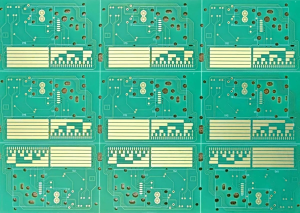
FR4 PCB
1. Introduction to FR4 PCB
FR4 PCB is a type of printed circuit board that is constructed using FR4, a glass-reinforced epoxy laminate material. The term “FR4” refers to the flame-retardant properties of the material, which are crucial for safety in many electronic applications. This material offers a good combination of electrical, mechanical, and thermal properties, making it ideal for a wide range of industries.
But here’s the kicker: FR4 is the go-to choice for most PCB designs, especially for those that require a balance between cost, performance, and reliability. FR4 PCBs are used in consumer electronics, automotive devices, medical equipment, and many other sectors, offering flexibility in both design and manufacturing processes. Engineers rely on FR4 to ensure that their PCBs function efficiently under normal operational conditions.
In this article, we will cover the unique properties that make FR4 an essential material, the numerous benefits it provides, and its various applications in modern electronics. By the end, you will have a comprehensive understanding of why FR4 continues to dominate the PCB industry.
Table 1: Key Features of FR4 PCB
| Property | Description | Impact on PCB Performance |
|---|---|---|
| Flame Retardant | FR4 is flame-retardant, ensuring safety | Enhances fire safety in electronics |
| Mechanical Strength | High strength-to-weight ratio | Provides structural support to the PCB |
| Electrical Conductivity | Excellent conductor of electricity | Essential for reliable signal transmission |
| Thermal Resistance | Good resistance to heat | Prevents overheating of the board components |
2. What is FR4 PCB?
FR4 PCB is a type of printed circuit board made from a specific material known as FR4. This material is an epoxy resin that is reinforced with glass fibers to enhance its mechanical strength and durability. The “FR” in FR4 refers to its flame-retardant properties, which make it suitable for use in electronic devices that need to meet safety standards.
What’s the real story? FR4 PCBs are not just about safety; they offer a well-rounded performance profile that makes them suitable for a wide range of electronic applications. They provide excellent electrical insulation, resistance to heat, and the ability to withstand environmental stress. FR4 is the ideal choice for most consumer electronics, power supplies, and automotive applications, providing engineers with a cost-effective yet reliable material to work with.
In the manufacturing of FR4 PCBs, the material is typically processed into thin layers that are stacked and bonded together with copper traces. These copper traces form the electrical pathways that connect the various components on the board. Once the design is complete, the PCB is tested to ensure that it meets the required electrical and mechanical standards.
Table 2: Components of FR4 PCB
| Component | Description | Function in the PCB |
|---|---|---|
| Copper Layer | Thin copper foil applied to the surface | Carries electrical signals between components |
| Glass Fibers | Reinforcement material inside the epoxy resin | Provides mechanical strength to the PCB |
| Epoxy Resin | A polymer matrix used to bond the glass fibers | Acts as an insulating layer for electrical separation |
3. Properties of FR4 PCBs
FR4 PCBs are known for their excellent combination of electrical, mechanical, and thermal properties. These properties make FR4 the material of choice for a wide range of electronic applications. The unique characteristics of FR4 ensure that it can withstand environmental conditions, including heat, humidity, and mechanical stress, while still providing high electrical performance.
But here’s the kicker: one of the standout features of FR4 is its high-temperature resistance. This property makes FR4 ideal for use in applications where the PCB needs to operate under heat stress, such as power electronics, automotive systems, and industrial equipment. Additionally, FR4 has a high glass transition temperature (Tg), which refers to the point at which the material starts to soften. This makes it durable and stable even in challenging thermal environments.
On the electrical side, FR4 is a good insulator, preventing electrical leakage between traces and components. This is particularly important in high-speed circuits where signal integrity is crucial. The mechanical properties of FR4 ensure that the PCB retains its structural integrity over time, even in the presence of mechanical vibrations or shocks.
Table 3: FR4 Properties and Benefits
| Property | Description | Benefits |
|---|---|---|
| High Thermal Resistance | Can withstand high temperatures | Prevents overheating in power electronics |
| Electrical Insulation | Excellent insulator of electricity | Ensures safe operation of circuits |
| Durability | Resistant to physical stress and wear | Increases the lifespan of the PCB |
| Flame Retardancy | Resistant to flames and heat | Essential for safety in electronic devices |
4. Benefits of Using FR4 PCBs
The benefits of using FR4 for PCB manufacturing are vast, making it one of the most popular choices among engineers and manufacturers. One of the key advantages of FR4 is its cost-effectiveness. It offers a good balance between price and performance, making it an ideal material for mass production of PCBs.
What’s the real story? FR4 is not only affordable but also reliable. Its ability to handle a wide range of environmental factors, including high temperatures, mechanical stress, and electrical interference, makes it perfect for use in various industries. FR4 also provides excellent electrical performance, which is crucial for maintaining the integrity of signals in high-speed and high-frequency applications.
In addition, FR4’s widespread availability and ease of manufacturing contribute to its popularity. It can be easily sourced from multiple suppliers and is compatible with most PCB manufacturing processes. This makes it an ideal choice for engineers looking to design cost-effective yet high-performance PCBs for consumer electronics, automotive devices, and medical equipment.
Table 4: Advantages of FR4 PCBs
| Benefit | Description | Application |
|---|---|---|
| Cost-Effective | Affordable material for mass production | Consumer electronics, appliances |
| Reliable Performance | Provides stability and reliability in various environments | Automotive, industrial equipment |
| Easy to Manufacture | Easily available and compatible with most manufacturing processes | Mass production of PCBs |
5. FR4 PCB vs Other Materials
When comparing FR4 to other PCB materials, it becomes clear why it is the go-to option for many applications. Other materials, such as PTFE (Polytetrafluoroethylene) or ceramics, offer specific advantages but often at a higher cost. PTFE, for example, is ideal for high-frequency applications due to its lower dielectric constant, but it is more expensive and difficult to manufacture.
But here’s the kicker: while PTFE and ceramics offer certain specialized advantages, FR4 stands out due to its overall versatility, performance, and cost-effectiveness. For most standard electronic applications, FR4 provides the ideal balance of performance, durability, and affordability. This makes it suitable for a wide range of industries, from consumer electronics to automotive and industrial applications.
FR4’s strength lies in its ability to perform well across a variety of conditions. While materials like PTFE excel in specific scenarios, FR4 remains the top choice for everyday PCB manufacturing due to its excellent combination of cost, performance, and ease of use.
Table 5: FR4 vs Other PCB Materials
| Material | Pros | Cons | Best Use Case |
|---|---|---|---|
| FR4 | Cost-effective, reliable, widely available | Limited in high-frequency applications | Consumer electronics, automotive |
| PTFE | Low dielectric constant, high-frequency performance | Expensive, difficult to manufacture | High-speed or RF circuits |
| Ceramics | Excellent for high-temperature applications | Expensive, brittle | Aerospace, military |
6. The FR4 PCB Manufacturing Process
The process of manufacturing FR4 PCBs involves several steps to ensure the material is shaped and assembled into the desired form. First, FR4 sheets are laminated with copper foil to create the base for the PCB. Then, the design is transferred onto the copper layer using photolithography, where traces are etched into the copper to form the necessary electrical pathways.
This is where it gets interesting… After the traces are created, the PCB is drilled to create holes for component placement. Vias, or conductive paths through the PCB, are then added to connect different layers of the board. Finally, the board is tested for electrical integrity and quality assurance before it is ready for use in electronic devices.
The entire process is automated in many cases, allowing for large-scale production of FR4 PCBs. This streamlined process makes FR4 a cost-effective material for mass production while maintaining high performance and reliability.
Table 6: Steps in FR4 PCB Manufacturing
| Step | Description | Purpose |
|---|---|---|
| Laminating | FR4 sheets laminated with copper foil | Creates the base material |
| Photolithography | Design transferred onto copper | Defines trace layout |
| Drilling | Holes drilled for component placement | Allows for component soldering |
| Testing | Electrical testing of the PCB | Ensures functionality |
7. Common Applications of FR4 PCBs
FR4 PCBs are used in a wide variety of industries, ranging from consumer electronics to automotive and medical devices. The versatility of FR4 allows it to be used in devices such as smartphones, laptops, power supplies, and medical equipment.
Ready for the good part? The automotive industry, for example, relies on FR4 PCBs for controlling engine systems, airbags, and entertainment systems. Similarly, in the medical field, FR4 PCBs are used in diagnostic equipment, where precision and reliability are paramount. In consumer electronics, FR4 PCBs are used in everything from smartphones to gaming consoles, where high performance and cost-effectiveness are essential.
As technology continues to advance, the demand for high-performance FR4 PCBs grows, driving further innovation in the manufacturing process and the materials used. FR4 will continue to play a key role in electronics for years to come.
Table 7: Common Applications of FR4 PCBs
| Industry | Application | Example Devices |
|---|---|---|
| Consumer Electronics | Smartphones, computers, gaming consoles | iPhones, laptops, video game systems |
| Automotive | Engine control, safety systems | Engine control units, airbag systems |
| Medical Devices | Diagnostic and monitoring equipment | MRI machines, blood glucose meters |
8. FR4 PCB in High-Frequency Applications
While FR4 is a highly versatile material, it does have limitations in high-frequency applications. The dielectric constant of FR4 is higher compared to materials like PTFE, which can cause signal degradation and loss at high frequencies. As a result, FR4 is generally not ideal for high-speed circuits, such as RF (radio frequency) and microwave applications.
But here’s the kicker: FR4 can still be used in many high-frequency applications, but it requires careful design considerations. For example, using shorter traces, optimizing impedance, and ensuring proper grounding can help mitigate some of the performance issues associated with high-frequency signals.
In applications where high-frequency signals are not critical, FR4 remains an excellent choice due to its availability, cost-effectiveness, and durability. However, for specialized RF applications, engineers may turn to other materials with lower dielectric constants, such as PTFE or ceramics.
Table 8: FR4 Performance in High-Frequency Applications
| Application | Impact of FR4 | Solution |
|---|---|---|
| High-Speed Circuits | Signal degradation due to higher dielectric constant | Use impedance control and short traces |
| RF Circuits | Limited performance in high-frequency range | Use PTFE or ceramic materials |
9. FR4 PCB in Power Electronics
FR4 PCBs are widely used in power electronics, where their ability to handle high currents and resist heat makes them ideal for power supplies and other high-power devices. The electrical properties of FR4 ensure efficient power distribution while maintaining stability and reliability.
This is where it gets interesting… In power electronics, FR4 PCBs are often designed with thicker copper layers to handle the increased current flow. The high thermal resistance of FR4 also helps dissipate the heat generated by power components, ensuring the longevity of the device. Power supplies, inverters, and battery management systems all benefit from the unique properties of FR4 PCBs.
Table 9: Use of FR4 in Power Electronics
| Device Type | FR4 Benefits | Application |
|---|---|---|
| Power Supplies | High thermal resistance, durability | DC-DC converters, AC-DC adapters |
| Inverters | Heat dissipation and structural strength | Solar inverters, motor drives |
| Battery Management | Electrical insulation and heat resistance | Lithium-ion battery chargers |
10. FR4 PCB for Flexible Designs
While FR4 is typically associated with rigid PCBs, it can also be used in flexible designs. Flexible PCBs, or flex circuits, are becoming increasingly popular in applications where space is limited, and the board needs to bend or flex. FR4 can be used for flexible circuits in a variety of consumer electronics and medical devices.
Ready for the good part? FR4 is combined with flexible substrates, such as polyimide, to create flexible boards that maintain the strength and performance of standard FR4 PCBs. While not as flexible as other materials specifically designed for flex circuits, FR4 offers a good compromise between performance, durability, and cost.
Table 10: FR4 in Flexible PCB Designs
| Feature | Description | Application |
|---|---|---|
| Flexibility | Combined with flexible substrates | Wearable electronics, medical devices |
| Durability | High mechanical strength | Compact, flexible consumer electronics |
| Cost-Effectiveness | More affordable than pure flex circuits | Mobile phones, laptops |
11. FR4 PCB and Environmental Considerations
FR4 is a popular choice for PCB manufacturing due to its strength and reliability. However, as environmental concerns grow, the sustainability of FR4 has come under scrutiny. FR4 is made from epoxy resin and glass fibers, which are non-biodegradable materials. The disposal of FR4 PCBs at the end of their life cycle can contribute to environmental waste.
What’s the real story? While FR4 is not the most eco-friendly material, there are efforts to improve its sustainability. Manufacturers are exploring ways to recycle FR4 PCBs and reduce the environmental impact of the material. Furthermore, new developments in eco-friendly materials for PCBs are underway, offering hope for a more sustainable future.
Table 11: Environmental Impact of FR4
| Factor | Impact | Potential Solutions |
|---|---|---|
| Non-Biodegradability | FR4 does not decompose naturally | Recycling programs, eco-friendly alternatives |
| Manufacturing Process | Requires energy-intensive processes | Use of renewable energy sources in production |
| End-of-Life Disposal | Contributes to e-waste | Develop recycling techniques for FR4 |
12. Advanced FR4 PCB Designs
As technology advances, the demand for more compact, efficient, and high-performance PCBs grows. This has led to innovations in FR4 PCB design, such as multi-layer PCBs, HDI (High-Density Interconnect) boards, and miniaturized components. FR4 is well-suited for these advanced designs due to its strength, reliability, and ease of use in high-density applications.
But here’s the kicker: advanced FR4 PCB designs allow for more complex circuitry in smaller spaces, making them ideal for modern electronic devices like smartphones, wearables, and IoT devices. These designs often use smaller traces and vias, and FR4’s high mechanical strength ensures the boards remain durable even with increased component density.
Table 12: Advanced FR4 PCB Design Features
| Design Feature | Benefit | Application |
|---|---|---|
| Multi-layer PCBs | Increased circuit density | Smartphones, tablets |
| HDI PCBs | Smaller vias and traces, higher performance | Wearables, high-speed devices |
| Miniaturized Components | Smaller, compact designs | IoT devices, embedded systems |
13. Testing and Quality Control for FR4 PCBs
Testing is essential to ensure that FR4 PCBs meet performance and safety standards. Electrical testing methods, such as in-circuit testing (ICT), and automated optical inspection (AOI) are commonly used to identify defects in PCB traces and component placements. Additionally, environmental tests ensure that FR4 PCBs can withstand the conditions they will be exposed to in their respective applications.
Ready for the good part? Quality control ensures that FR4 PCBs perform as intended in real-world conditions. Manufacturers test for a wide range of factors, including electrical continuity, signal integrity, and heat resistance. This testing process helps minimize the risk of failures and ensures that the final product meets the required standards.
Table 13: FR4 PCB Testing Methods
| Test Method | Purpose | Benefits |
|---|---|---|
| In-Circuit Testing (ICT) | Checks component functionality | Detects faults early |
| Automated Optical Inspection (AOI) | Inspects for visual defects | Automated, high-accuracy checks |
| Environmental Testing | Simulates real-world conditions | Ensures durability and performance |
14. Troubleshooting FR4 PCB Issues
Even with the best design practices, issues can arise during the manufacturing process or after deployment. Common problems with FR4 PCBs include poor solder joints, signal interference, and trace breakage. Troubleshooting these issues involves thorough testing, inspection, and sometimes redesigning certain aspects of the board to ensure optimal performance.
This is where it gets interesting… Many problems with FR4 PCBs can be traced back to design flaws or poor manufacturing processes. For instance, improper trace width or via size can lead to overheating or signal degradation. Identifying and correcting these issues early can save time and costs in the long run.
Table 14: Common FR4 PCB Issues and Solutions
| Issue | Cause | Solution |
|---|---|---|
| Poor Signal Integrity | Incorrect trace width, impedance mismatch | Use controlled impedance design |
| Solder Joint Issues | Poor soldering techniques or components | Improve soldering process, inspect thoroughly |
| Trace Breakage | Overheating or mechanical stress | Ensure proper trace width, use thicker copper layers |
15. Conclusion
In conclusion, FR4 PCBs offer an ideal balance of cost, performance, and durability, making them the material of choice for a wide range of applications. Whether you’re designing consumer electronics, automotive devices, or medical equipment, FR4 provides the reliability and functionality needed for high-performance circuits. By understanding the properties, benefits, and design
considerations of FR4 PCBs, engineers can create innovative and efficient designs that meet the demands of modern electronics.
FAQ Section
Q1: What is FR4 PCB?
FR4 PCB is a type of printed circuit board made from FR4, a flame-retardant, glass-reinforced epoxy laminate material used widely in the electronics industry.
Q2: How does FR4 compare to other PCB materials?
FR4 offers a good balance of electrical performance, mechanical strength, and cost-effectiveness, making it ideal for most electronic applications compared to more specialized materials.
Q3: What are the benefits of using FR4 PCBs?
FR4 offers excellent thermal resistance, electrical insulation, and durability, making it suitable for a wide range of applications, including consumer electronics and industrial systems.
Q4: Can FR4 be used in high-frequency circuits?
FR4 is suitable for many applications but has limitations in high-frequency circuits due to its higher dielectric constant. For high-speed or RF applications, materials like PTFE may be preferred.
Q5: How is the FR4 PCB manufacturing process carried out?
The FR4 PCB manufacturing process involves laminating FR4 sheets with copper foil, transferring the design via photolithography, drilling for component placement, and conducting rigorous testing for quality.

- long board pcb
- Flexible PCBs
- Special PCB
- Express Printed Circuit Board
- Pcb Prototype
- LED PCB
- PCB
- Printed Circuit Board
- Pcb meaning
- Pcb manufacturer
- Rigid pcb board
- Rigid Flex PCB
 Quote
Quote
 E-mail