1. Introduction: Understanding the Challenge of Printed Circuit Board Heating
In the rapidly evolving landscape of electronics, managing heat generation has become a pivotal concern for engineers and designers. As devices continue to shrink in size and expand in functionality, the thermal stress placed on internal components has increased dramatically. Among the many elements affected by this shift, the printed circuit board (PCB) stands at the forefront. The issue of printed circuit board heating, though not new, has escalated in complexity with the integration of high-power components, multilayered architectures, and greater circuit densities.
Modern electronic systems—from consumer gadgets to high-frequency communication modules—depend heavily on PCBs not just as a structural platform, but also as a conduit for signal transmission, power distribution, and heat dissipation. As power levels rise and design margins narrow, thermal management becomes both a performance issue and a reliability imperative. Excessive heating can lead to thermal fatigue, delamination of layers, solder joint cracking, and ultimately device failure.
While designers often concentrate on electronic functionality, effective heat management must be baked into the PCB development process from the very beginning. The ramifications of neglecting thermal control extend beyond product longevity; they can influence energy efficiency, safety certifications, and even user satisfaction. Therefore, any forward-thinking design methodology must consider not just how to conduct signals, but also how to dissipate the heat those signals generate.
The complexity of addressing printed circuit board heating lies in its multifactorial nature. It is not merely a function of power density or component count. Instead, it arises from an intricate interplay between materials, geometry, airflow, environmental conditions, and usage cycles. The result is that one-size-fits-all solutions are ineffective, and custom approaches tailored to specific applications are essential.
This article aims to dissect the issue from multiple angles—material selection, structural layout, active and passive cooling technologies, simulation tools, and manufacturing practices. It presents not only technical solutions, but also offers critical analysis of how different strategies align with evolving industry demands. Throughout the discussion, the emphasis remains on practical, scalable, and cost-effective means to control the phenomenon of printed circuit board heating in real-world applications.
What’s particularly compelling about this area of research is that it sits at the crossroads of thermal engineering, materials science, and electronics innovation. Solving the problem of heat requires engineers to think beyond circuit diagrams and consider physical principles such as conduction, convection, and radiation. It invites a multidisciplinary mindset and rewards those who integrate mechanical and electronic perspectives early in the design process.
This opening chapter serves as the foundation for a comprehensive exploration of the strategies available to tackle printed circuit board heating. The goal is to offer readers not just a list of potential fixes, but a framework for systematically addressing thermal issues through informed design, validated testing, and proactive innovation.
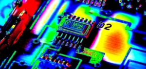
printed circuit board heating
2. Root Causes of Printed Circuit Board Heating in Modern Electronics
Understanding the root causes of printed circuit board heating is essential for developing effective mitigation strategies. As electronic systems have grown in complexity and performance, the amount of heat generated internally has followed a steep upward trajectory. This section explores the key factors that contribute to heating in PCBs and how each plays a role in shaping thermal behavior across various application environments.
2.1 High Power Density Components
One of the most direct contributors to excessive heat in PCBs is the integration of high power density components. Power transistors, voltage regulators, and RF amplifiers, for instance, can generate significant amounts of localized heat during operation. As modern systems demand more processing power within tighter spatial constraints, these components are increasingly packed onto smaller board areas. The result is a spike in localized heating that is difficult to dissipate using traditional means.
Thermal hotspots develop around such components, creating gradients that stress the board mechanically and electrically. Without adequate design interventions—such as heat sinks, thermal vias, or copper pours—these areas become thermal bottlenecks, raising the overall board temperature and accelerating aging in sensitive components.
2.2 Inadequate Thermal Conductivity of PCB Materials
The base materials used in PCB construction, such as FR-4, have relatively low thermal conductivity compared to metals or ceramic substrates. While these materials are electrically insulative and cost-effective, their inability to efficiently transfer heat away from critical zones is a key contributor to printed circuit board heating.
The situation is further exacerbated in multilayer designs, where heat generated in internal layers struggles to escape to the board surface or ambient environment. This thermal entrapment leads to increased internal temperatures, affecting both component performance and structural stability. Material innovation—such as the use of metal-core PCBs—has helped alleviate this issue in some sectors, but cost and manufacturability remain limiting factors.
2.3 Poor PCB Layout and Design Practices
Thermal management is closely tied to layout strategy. Poor component placement, inadequate copper area for heat spreading, and inefficient via usage can significantly elevate temperatures on a board. For example, placing heat-generating components near board edges or adjacent to thermal-sensitive circuits can lead to uneven heat distribution, which may compromise functionality or reliability.
A well-thought-out layout that considers airflow paths, heat sinks, and the thermal characteristics of neighboring components is crucial. Often, thermal concerns are addressed too late in the design cycle, limiting the ability to make impactful changes without costly redesigns.
2.4 Overloaded Traces and Narrow Copper Widths
Electrical traces on a PCB not only carry current—they also act as conductors of heat. When traces are undersized for the amount of current they are intended to carry, they generate resistance-related heating. The Joule heating effect (I²R losses) becomes significant, especially in high-current applications, such as power distribution boards and LED drivers.
In such cases, increasing trace width, using thicker copper layers, or implementing dedicated ground and power planes becomes necessary. Failing to do so can result in trace burnout or thermal damage to adjacent components and substrate layers.
2.5 Environmental and Operational Conditions
The ambient conditions under which a PCB operates also contribute to thermal behavior. Devices used in high-temperature environments, such as automotive or aerospace systems, already begin operation at elevated baseline temperatures. Add to that the internal heat generated by the circuit, and the result is often overheating.
Furthermore, PCBs enclosed in poorly ventilated housings or tightly sealed enclosures may not have sufficient pathways for convection or radiation to remove heat effectively. This isolation increases the dependence on board-level thermal solutions and drives up the importance of passive and active cooling measures.
2.6 High-Frequency Switching and Signal Processing
The proliferation of high-speed and high-frequency circuits introduces another dimension to printed circuit board heating. Fast switching transients in digital systems, RF losses in analog circuits, and eddy currents in high-frequency planes all result in energy dissipation in the form of heat.
Particularly in densely packed systems with extensive power and ground planes, these high-frequency losses accumulate, elevating internal board temperatures. The combination of skin effect and dielectric losses further complicates heat flow and requires careful attention during material selection and stack-up planning.
This section illustrates how a combination of component characteristics, material properties, design approaches, and environmental factors all contribute to printed circuit board heating. Identifying and understanding these root causes is the first step toward engineering effective solutions, which will be discussed in the next sections.
3. Material-Level Solutions for Printed Circuit Board Heating
To effectively address the challenge of printed circuit board heating, it is critical to begin with the fundamental building blocks of the board itself—its materials. The thermal performance of a PCB is largely determined by the thermal conductivity and structural design of its constituent layers. When material selection is made with thermal management in mind, it can significantly mitigate the risk of overheating and contribute to the long-term reliability of the system.
In this section, we explore a range of material-level solutions that target heat dissipation directly at the source. These innovations do not rely on mechanical additions such as fans or heat sinks but instead enhance the intrinsic thermal capabilities of the board.
3.1 High Thermal Conductivity Substrates for Printed Circuit Board Heating Control
Standard PCB substrates like FR-4 are widely used due to their affordability and versatility, yet they exhibit low thermal conductivity—typically around 0.3–0.4 W/m·K. This limits their ability to dissipate heat, especially in high-power or high-frequency applications. To improve thermal transfer, alternative substrates with higher conductivity have been developed.
One such solution is the use of ceramic-based substrates such as aluminum oxide (Al₂O₃) and aluminum nitride (AlN), which offer conductivities in the range of 20–170 W/m·K. These materials are particularly favored in high-reliability sectors like aerospace, automotive, and telecommunications, where thermal performance cannot be compromised.
Another approach is the use of thermally enhanced epoxies or filled polymer systems. These materials integrate conductive fillers such as boron nitride or graphene into the resin matrix, increasing thermal pathways without significantly impacting electrical insulation.
Choosing a high-conductivity substrate reduces internal temperature rise and provides a uniform thermal profile across the board, thereby reducing the likelihood of localized stress or delamination.
3.2 Metal Core PCBs as a Defense Against Printed Circuit Board Heating
Metal core printed circuit boards (MCPCBs) provide a powerful material-level strategy for heat management. Typically composed of a dielectric insulating layer sandwiched between a copper circuit layer and a metallic core (usually aluminum or copper), MCPCBs excel in transferring heat away from heat-generating components.
The metal core acts as a heat spreader, drawing thermal energy away from sensitive zones and distributing it over a broader area. This structure is especially valuable in applications such as LED lighting, power electronics, and motor controllers, where continuous operation under high thermal load is expected.
MCPCBs can be designed as single-layer or multi-layer structures, depending on complexity and heat dissipation requirements. Although more expensive than traditional FR-4 boards, their superior thermal performance often justifies the investment, particularly in mission-critical applications.
3.3 Thermally Enhanced Vias and Layers in Printed Circuit Board Heating Management
Beyond the base materials, the construction and layering of the PCB play a vital role in thermal conductivity. One of the most widely used methods to improve vertical heat transfer in multilayer PCBs is the implementation of thermally enhanced vias.
Thermal vias are plated through-holes that connect the heat-generating surface layer to internal or backside copper planes, allowing heat to bypass thermally resistive layers. These vias are often filled with conductive materials—such as copper epoxy paste—or left open to allow solder to wick into them during assembly, further enhancing thermal conductivity.
Another enhancement involves using heavy copper layers (up to 6 oz or more) for power and ground planes. These layers not only improve current-carrying capacity but also serve as excellent heat spreaders, helping to equalize temperature across the PCB surface.
Stack-up configurations can also be optimized to place high-conductivity layers closer to heat-sensitive components, thereby shortening the thermal path to ambient. Additionally, advanced fabrication techniques now allow for embedded copper coins and graphite inserts that act as local heat sinks built into the board.
By strategically selecting materials and optimizing internal PCB structures, engineers can establish a strong foundation for controlling printed circuit board heating before turning to mechanical cooling methods. These material-level solutions offer passive, scalable approaches that blend well with modern design practices and provide long-term benefits in performance and reliability.
4. Design Strategies to Mitigate Printed Circuit Board Heating
Beyond materials, the design phase plays a pivotal role in how effectively a PCB can manage thermal loads. Proper design can significantly reduce the risks associated with printed circuit board heating without the need for expensive post-production solutions. In this section, we delve into the key design methodologies that engineers and layout professionals can use to minimize heat buildup and ensure optimal thermal distribution.
These design strategies range from component placement to trace routing, and from thermal via implementation to software-assisted thermal simulation—all of which contribute to a more thermally efficient board.
4.1 Component Placement Optimization in Printed Circuit Board Heating Control
The layout of components on a PCB directly affects heat generation and dissipation. Placing heat-generating components such as power MOSFETs, regulators, and processors near the board center or away from airflow paths can trap heat and cause thermal hotspots. Conversely, strategically locating these components near board edges or in areas with optimal airflow can significantly enhance heat evacuation.
Grouping high-power components together and aligning them with thermal paths such as heat sinks or metal cores enables more focused cooling. Additionally, sensitive analog or temperature-critical ICs should be distanced from high-temperature zones to avoid thermal interference and signal instability.
Designers must also consider orientation: aligning components with long heat-generating surfaces in the direction of airflow (natural or forced) can increase convective efficiency.
4.2 Copper Area Maximization and Trace Design for Printed Circuit Board Heating Reduction
Copper is not just a conductor of electricity; it is also a powerful conductor of heat. In regions where thermal buildup is a concern, increasing the copper area—through wider traces, solid copper pours, and dedicated ground/power planes—can significantly help in spreading heat.
For instance, wide traces connected to high-current paths act as both electrical and thermal conductors, reducing Joule heating (I²R losses). Pouring copper around power components or routing traces through internal layers connected via thermal vias allows heat to flow laterally and vertically throughout the board.
To minimize printed circuit board heating from trace-related losses, designers often use:
-
Wider traces for high-current paths
-
Thermal relief pads for balancing heat dissipation and solderability
-
Shorter trace lengths in high-power applications to reduce resistance
4.3 Thermal Via Arrays and Heat Spreader Integration in Printed Circuit Board Heating Designs
Thermal vias are vital in multilayer PCBs for conducting heat from the top layer—where most active components reside—to internal ground or metal layers that can serve as heat spreaders. These vias are typically placed under or around heat sources and can be either filled (solid copper or conductive epoxy) or open to allow for better heat conduction.
Dense thermal via arrays under components such as QFNs, BGAs, or high-power LEDs effectively shuttle heat through the board and into copper planes or metal cores. Spreading this heat over a broader area helps lower the temperature in the critical hotspot region.
In some designs, large surface-mounted heat spreaders made of copper or aluminum can be soldered directly onto thermal vias or pads to function as passive cooling devices, increasing surface area and facilitating heat dissipation to ambient air.
4.4 Layer Stack-Up Planning in Printed Circuit Board Heating Management
The layer stack-up configuration of a PCB also plays a critical role in thermal performance. Designers can strategically position power and ground planes to act as internal heat spreaders, ensuring efficient horizontal heat conduction.
By placing high-power signal layers closer to copper planes and optimizing the thickness of dielectric layers, heat flow paths are shortened, reducing the thermal resistance from the component to the exterior. In HDI (High-Density Interconnect) PCBs, careful stack-up planning becomes even more essential, as the compact nature of the board reduces convection surfaces.
Designs may also include embedded heatsinks, metal coins, or graphite inserts directly into the stack-up to deal with localized heating in performance-intensive applications.
4.5 CAD Tools and Thermal Simulation for Printed Circuit Board Heating Prediction
Modern PCB design tools offer simulation features that allow thermal modeling of a board before physical fabrication. These tools, such as those from ANSYS, Altium Designer, Cadence, and Mentor Graphics, can simulate the flow of heat through the board based on material properties, component power dissipation, and environmental conditions.
By leveraging thermal simulation during the early design phase, engineers can identify hotspots, test the impact of layout changes, and iteratively optimize thermal performance. This approach helps minimize redesigns, production delays, and field failures.
Such simulations can also analyze the effects of airflow, mechanical heat sinks, and casing materials, enabling a holistic view of the thermal ecosystem in which the board operates.
5. Thermal Interface Materials and Mechanical Solutions for Printed Circuit Board Heating
While material selection and PCB layout design can address a significant portion of heat management challenges, they may not suffice for high-power applications or densely packed assemblies. In such cases, engineers turn to thermal interface materials (TIMs) and mechanical cooling mechanisms to further mitigate printed circuit board heating. These solutions provide direct, active, or passive thermal pathways between heat sources and the surrounding environment, enhancing overall system efficiency.
This section introduces commonly used TIMs and mechanical strategies such as heat sinks, fans, and enclosure design—each vital in reducing the thermal burden on a working PCB.
5.1 Thermal Interface Materials in Printed Circuit Board Heating Management
Thermal interface materials serve as conductive bridges between heat-generating components and heat-dissipating surfaces, such as heat sinks or metal enclosures. Without these materials, microscopic air gaps between mating surfaces would impede heat transfer due to air’s poor thermal conductivity.
Common TIMs include:
-
Thermal greases and pastes: Used between ICs and heat sinks; they provide excellent surface conformity and minimize thermal resistance.
-
Thermal pads: Pre-formed materials made from silicone, graphite, or phase-change materials that are easy to apply during assembly.
-
Gap fillers: Used in uneven surfaces or where vibration and shock resistance is necessary.
-
Phase-change materials: These TIMs become softer and spread more evenly with heat, optimizing contact area over time.
-
Graphite-based sheets: Used where a combination of flexibility, electrical insulation, and thermal performance is needed.
The effectiveness of a TIM is measured by its thermal conductivity (W/m·K) and thermal resistance (°C·cm²/W). Lower resistance and higher conductivity generally yield better performance.
Integrating the right TIM is essential when managing printed circuit board heating, particularly in high-frequency RF circuits, power electronics, and CPUs.
5.2 Heat Sink Implementation for Printed Circuit Board Heating Reduction
Heat sinks are among the most straightforward and effective tools for controlling PCB temperatures. Attached directly to high-power components or thermally conductive regions of the PCB, heat sinks enhance surface area, facilitating heat dissipation into ambient air.
Types of heat sinks used in PCB applications include:
-
Stamped or extruded metal heat sinks: Typically made of aluminum or copper and mounted using clips, screws, or thermal adhesive.
-
Bonded-fin and folded-fin heat sinks: Provide higher surface area and improved airflow interaction.
-
Integrated PCB heat sinks: Copper coins or thick internal copper layers designed into the board stack-up.
Designers must consider thermal resistance, airflow direction, and orientation of fins for maximum efficiency. For instance, vertical fin alignment is optimal for natural convection, while horizontal or forced convection systems might benefit from alternative geometries.
Heat sinks are particularly effective when combined with TIMs to reduce thermal resistance at the interface point.
5.3 Active Cooling Systems for Printed Circuit Board Heating Control
When passive cooling is insufficient, active cooling mechanisms such as fans, blowers, and thermoelectric modules become necessary.
-
Fans and blowers: Provide directed airflow across the PCB, increasing convective heat transfer. Strategic placement ensures uniform cooling and prevents recirculation of hot air.
-
Thermoelectric coolers (TECs or Peltier devices): Useful in highly sensitive applications. They pump heat from the cold side (component) to the hot side (dissipation surface) using electrical energy.
-
Liquid cooling: Although rare in traditional PCBs, it’s gaining ground in high-density, high-power systems like data center boards, where liquid coolant runs through channels embedded in or adjacent to the board.
Active cooling allows fine-tuned temperature control but introduces complexity in terms of power consumption, noise, and mechanical integration. It’s particularly useful in harsh environments or continuous high-load conditions where passive methods alone cannot maintain thermal stability.
5.4 Enclosure Design and Environmental Control in Printed Circuit Board Heating Management
The enclosure that houses a PCB greatly affects its thermal performance. A well-designed enclosure considers airflow, material properties, and heat conduction pathways.
Key enclosure strategies include:
-
Vented or slotted housings to promote natural or forced airflow.
-
Metal enclosures to aid conduction and shield from electromagnetic interference (EMI).
-
Internal fans or ducts to guide cool air over critical PCB zones.
-
Isolation chambers to separate high-heat and low-heat sections of a system.
-
Integration of heat pipes from the PCB to the enclosure walls, transferring heat outward.
Environmental controls such as humidity regulation, dust filters, and ingress protection (IP ratings) also impact thermal performance by maintaining optimal operating conditions and preventing overheating due to clogged vents or conductive debris.
Mechanical and thermal interface solutions offer reliable, scalable methods for controlling printed circuit board heating, especially when integrated with material and layout optimizations. In high-power electronics, where thermal stress can quickly erode performance and longevity, these solutions are not optional—they are essential.
6. Component-Level Techniques for Reducing Printed Circuit Board Heating
In addition to material choices, layout strategies, and mechanical solutions, the thermal performance of a printed circuit board can be greatly influenced by the specific components used and how they are selected or configured. This section explores component-level strategies for minimizing printed circuit board heating, focusing on methods that reduce power dissipation, optimize electrical efficiency, and directly lower thermal output at the source.
These techniques are especially critical in compact designs and high-reliability systems where heat must be controlled at the micro level.
6.1 Low Power and High Efficiency Components in Printed Circuit Board Heating Management
One of the most effective ways to minimize heat generation is to choose components that consume less power or operate more efficiently. Power losses in electronic components manifest primarily as heat, and selecting efficient alternatives can have an immediate and measurable impact on board temperature.
Examples include:
-
Low-dropout (LDO) vs. switching regulators: Switched-mode power supplies (SMPS) offer far higher efficiency compared to LDOs, which dissipate excess voltage as heat.
-
MOSFETs with low R<sub>DS(on)</sub> values: Lower on-resistance results in less conduction loss during switching operations.
-
LEDs with higher luminous efficacy: These produce more light per unit of power, reducing unnecessary heating.
-
High-efficiency microcontrollers and FPGAs: Modern processors with deep sleep modes, power gating, and optimized clock trees help reduce active and idle power consumption.
Using such components does not just minimize printed circuit board heating—it can also reduce the need for oversized cooling systems, leading to lower cost and weight.
6.2 Power Management ICs for Printed Circuit Board Heating Control
Proper power regulation and distribution is another layer of defense against excessive heating. Power Management Integrated Circuits (PMICs) and voltage regulators with built-in thermal management features can help distribute load efficiently and react dynamically to thermal conditions.
Techniques include:
-
Dynamic voltage and frequency scaling (DVFS) to reduce energy usage during low-load periods.
-
Load sharing and current balancing across multiple regulators to avoid overheating a single unit.
-
Slew rate control to limit current surges that lead to localized heating.
-
Thermal shutdown and derating functions to protect sensitive devices from thermal stress.
Many modern PMICs can monitor their own temperature and provide data back to the system for adaptive control, enabling software-level thermal management as well.
6.3 Component Packaging Considerations in Printed Circuit Board Heating Scenarios
The physical package of a component plays a crucial role in how well it dissipates heat. When addressing printed circuit board heating, it’s not just the part’s electrical characteristics that matter, but also how heat escapes from its body.
Important packaging options include:
-
Thermally enhanced packages: Devices with exposed pads (e.g., QFN, PowerSO, D²PAK) that allow direct soldering to PCB copper for improved thermal transfer.
-
Flip-chip BGA: Offers excellent thermal paths due to shorter die-to-package connections and direct contact with substrate layers.
-
Metal-can or TO packages: Used in RF or power transistor applications for their excellent heat conduction.
Designers must evaluate the thermal impedance of packages and verify whether the surrounding PCB layout supports proper heat spreading from the pad to the internal planes or heat sinks.
6.4 Clock and Signal Frequency Optimization to Minimize Printed Circuit Board Heating
The frequency at which a system operates influences not only its performance but also its thermal footprint. Higher clock frequencies lead to higher switching losses, increased electromagnetic emissions, and greater power consumption, all contributing to increased heat.
To counteract this:
-
Use only the necessary clock speed for each subsystem.
-
Implement dynamic clock scaling, reducing frequencies when full speed is not required.
-
Select low-power oscillators and clock distribution ICs with reduced idle consumption.
Additionally, minimizing unnecessary signal transitions, especially in digital buses and high-speed interfaces, can further suppress heat generation at the signal layer.
6.5 Thermal Monitoring ICs for Printed Circuit Board Heating Supervision
Modern electronics increasingly incorporate thermal sensors or temperature-monitoring ICs to manage real-time temperature data. These components provide essential feedback for software or hardware-based thermal management systems.
Common features include:
-
I²C or SPI interfaces to transmit temperature data to the system controller.
-
Programmable alert thresholds for automatic shutdown or throttling.
-
Multi-zone temperature sensing for large boards or critical components like CPUs and battery packs.
By integrating temperature sensors near hot spots, engineers can design closed-loop systems that adapt fan speeds, current draw, or processor load based on real-time thermal conditions—effectively extending the board’s operating life and reliability.
Component-level techniques are a highly efficient front-line strategy for reducing printed circuit board heating. These solutions not only improve thermal behavior at the source but also enhance electrical performance, reduce power supply demands, and minimize the burden on board-level or mechanical cooling systems.
7. Environmental and Application-Specific Considerations for Printed Circuit Board Heating
While material, design, and component-level strategies are critical for managing internal thermal challenges, the external environment and intended application of a PCB also play a major role in influencing the severity of printed circuit board heating. Conditions such as ambient temperature, altitude, humidity, and enclosure configuration can intensify or alleviate thermal stress. Similarly, different industries impose distinct performance and reliability demands that directly affect thermal design strategies.
In this section, we explore how environmental conditions and application-specific requirements shape the thermal behavior of PCBs and dictate the approaches engineers must adopt to ensure reliable operation in diverse scenarios.
7.1 High-Temperature Environments and Printed Circuit Board Heating Challenges
Operating in high ambient temperatures significantly limits a PCB’s ability to dissipate internally generated heat. In such conditions, the temperature gradient between the board and its surroundings is reduced, making passive cooling less effective and accelerating component aging.
Key challenges include:
-
Reduced cooling headroom: Components operate closer to their maximum rated junction temperatures.
-
Material degradation: Prolonged exposure to high temperatures can lead to delamination, dielectric breakdown, or warping.
-
Increased leakage currents in semiconductors, leading to higher power consumption and more heat generation.
To mitigate these effects, designers working with printed circuit board heating in high-temperature environments often use:
-
High-Tg and high-CTI substrates (e.g., polyimide, ceramic-based laminates).
-
Forced-air or liquid cooling systems.
-
Heat-spreading techniques such as thermal vias and copper planes.
-
Thermal derating of components to reduce stress during operation.
Applications include industrial automation near furnaces, oil drilling electronics, and avionics in hot climates.
7.2 Printed Circuit Board Heating in High-Altitude and Low-Pressure Applications
At higher altitudes, reduced air pressure lowers the density of the atmosphere, significantly decreasing the effectiveness of convective cooling. This can make even moderate heat loads problematic, especially in systems with limited airflow.
Challenges include:
-
Weakened heat transfer: Natural convection is less effective, requiring active cooling systems or larger heat sinks.
-
Corona discharge risk in high-voltage circuits due to thinner air.
-
Increased thermal insulation if enclosures are sealed without internal ventilation.
Thermal strategies in these cases include:
-
Oversizing passive cooling components.
-
Employing vacuum-compatible TIMs and materials.
-
Designing for low outgassing and expansion rates.
-
Using pressure-compensated enclosures and thermal cycling qualification.
Typical use cases include aerospace systems, satellites, and avionics—where printed circuit board heating must be tightly controlled in the absence of effective convective paths.
7.3 Printed Circuit Board Heating in Moisture-Prone and Corrosive Environments
High humidity and corrosive atmospheres introduce both electrical and thermal risks to PCBs. Moisture can condense on heated components, altering thermal conductivity and potentially triggering short circuits or corrosion.
Specific thermal concerns include:
-
Condensation on hot components, causing localized thermal shocks during startup or cooling.
-
Corrosion at solder joints, increasing resistance and local heating over time.
-
Moisture-driven delamination, which affects mechanical integrity and heat dissipation.
To address printed circuit board heating in such environments, protective measures include:
-
Applying conformal coatings (e.g., silicone, acrylic, or parylene).
-
Designing venting systems that allow moisture escape without sacrificing thermal flow.
-
Sealing enclosures with breathable membranes that equalize pressure while blocking liquids.
-
Using corrosion-resistant components and coatings on heat sinks and other metal surfaces.
These precautions are vital in marine electronics, outdoor telecom systems, and chemical plant automation.
7.4 Application-Specific Thermal Design for Printed Circuit Board Heating Control
The nature of the end product heavily dictates the required thermal performance of the PCB. Thermal margins, response times, and allowable failure rates vary between consumer products and mission-critical systems.
Considerations by industry include:
-
Consumer electronics: Compact form factors necessitate efficient passive thermal paths, minimal fan use, and good material selection.
-
Automotive electronics: Must survive wide thermal swings, vibration, and proximity to engine heat; thermal cycling and rapid dissipation are crucial.
-
Medical devices: Require stable, predictable thermal profiles to avoid harm to patients or errors in diagnostics.
-
Military and defense: Demand ruggedness, redundancy, and extreme temperature tolerance under battlefield conditions.
In each case, thermal simulation, reliability testing, and certification standards (like IPC-9592 for power conversion devices) guide the engineering decisions to manage printed circuit board heating effectively.
By understanding and anticipating environmental and application-specific thermal loads, engineers can design PCBs that maintain performance and longevity even under extreme or unusual conditions. These contextual considerations are not peripheral—they are often decisive in determining the success of a thermal management strategy.
8. Simulation, Testing, and Validation Techniques for Printed Circuit Board Heating
Accurately predicting and verifying thermal performance is critical when designing for reliable operation and long-term durability. Effective simulation and validation of printed circuit board heating behavior ensure that theoretical strategies translate into real-world effectiveness. This section explores the tools and methodologies used to evaluate thermal performance during both the design and production phases, allowing engineers to identify hot spots, improve layout, and validate thermal control mechanisms under worst-case conditions.
8.1 Thermal Simulation Software for Printed Circuit Board Heating Prediction
Before a PCB is manufactured, designers can simulate its thermal behavior using specialized software tools. These simulations provide insight into heat flow, component temperatures, and airflow effects, enabling optimization before prototyping.
Popular tools include:
-
ANSYS Icepak: Used for comprehensive thermal modeling, especially in complex enclosures or high-density designs.
-
Mentor Graphics FloTHERM: Offers system-level thermal analysis with PCB integration and airflow modeling.
-
SolidWorks Flow Simulation: Suitable for mechanical and electronic integration scenarios.
-
Altium Designer and Cadence Celsius: Integrate electrical and thermal co-simulation for early-stage design decisions.
Thermal simulation helps visualize:
-
Heat distribution maps
-
Thermal impedance paths
-
Airflow vs. temperature correlation
-
Effectiveness of heat sinks, vias, and thermal planes
Using these tools during design helps prevent late-stage thermal failures and ensures the board meets temperature limits for reliability.
8.2 Prototyping and Infrared Thermography in Printed Circuit Board Heating Assessment
Once a prototype is available, physical measurement techniques offer real-time validation of thermal predictions. Infrared (IR) thermography is one of the most widely used non-contact methods for observing thermal behavior across the surface of a powered PCB.
Key benefits:
-
Visual identification of hot spots
-
Verification of component junction temperatures
-
Comparison of measured vs. simulated results
High-resolution IR cameras provide thermal images during operation, enabling engineers to identify areas of concern such as overheating regulators, inefficient copper areas, or poorly placed heat sinks.
This step is especially important for confirming assumptions made during simulation and catching heat-related problems that may arise from soldering, material flaws, or component tolerances.
8.3 Thermal Profiling and Data Logging for Printed Circuit Board Heating Analysis
Beyond surface imaging, embedded thermal profiling enables precise data collection during stress testing or real-world operation. This often involves placing thermocouples at key locations on the PCB to record temperature changes over time.
Applications include:
-
Thermal cycling tests to evaluate fatigue due to expansion/contraction.
-
Burn-in tests where boards are operated at elevated loads and temperatures to accelerate failure.
-
Data logging during field trials to monitor long-term temperature trends.
Modern systems use wireless or USB-connected profilers that can be inserted into test chambers or real enclosures, providing a deeper understanding of how printed circuit board heating evolves over time and under varying operational modes.
8.4 Computational Fluid Dynamics (CFD) in Printed Circuit Board Heating Design
For enclosures and systems where airflow is critical, Computational Fluid Dynamics (CFD) tools help model the interaction between airflow, convection, and PCB surface temperatures. These simulations are essential when natural convection or fan-based cooling is employed.
CFD tools such as:
-
SimScale
-
COMSOL Multiphysics
-
Autodesk CFD
allow engineers to:
-
Optimize vent placement and size.
-
Simulate fan speed and turbulence.
-
Predict how different enclosure geometries affect cooling.
CFD results can reveal zones of recirculating hot air or blocked vents, leading to improvements in both the PCB and housing designs to better manage heat dissipation.
8.5 Standards and Reliability Criteria for Printed Circuit Board Heating Testing
To ensure safety and reliability, PCBs must meet specific thermal standards and regulatory benchmarks. Organizations like IPC and JEDEC provide guidelines that help engineers define test conditions and pass/fail criteria.
Relevant standards include:
-
IPC-2221: General design standard including thermal management rules.
-
JEDEC JESD51 series: Procedures for measuring thermal resistance of semiconductor devices.
-
UL 796 and 94: Standards for flammability and thermal safety of PCBs.
-
MIL-STD-810: Military standard that includes thermal cycling and high-temperature stress protocols.
Adhering to these standards ensures that printed circuit board heating is not just managed but rigorously verified to comply with operational safety, customer expectations, and long-term reliability goals.
Simulation, testing, and validation are not one-time tasks but integral processes that span the full development lifecycle of a PCB. By combining predictive modeling with real-world verification, engineers can confidently deploy thermal strategies that withstand operational demands and environmental stress.
9. Case Studies and Real-World Implementations of Printed Circuit Board Heating Solutions
Understanding the theory behind thermal management is vital, but real-world implementation brings valuable insight into how printed circuit board heating solutions are applied across industries. This section presents multiple case studies illustrating how different thermal management techniques have been successfully used to address overheating issues in various electronic products. These examples demonstrate the practical decision-making, challenges encountered, and innovative adaptations used to keep PCBs within safe operating temperatures under realistic conditions.
9.1 Automotive Control Units: Printed Circuit Board Heating in Harsh Environments
Background: An automotive electronics company faced failures in engine control units (ECUs) used near high-temperature areas such as turbochargers.
Challenges:
-
High ambient temperature (>125°C).
-
Limited airflow within sealed automotive enclosures.
-
Exposure to mechanical shock and vibration.
Thermal Solution:
-
Shifted to high-Tg FR-4 material with improved delamination resistance.
-
Embedded thermal vias under high-power ICs to enhance heat flow to internal copper layers.
-
Integrated aluminum heat sinks bonded via thermally conductive adhesives.
-
Added copper pours for even heat distribution and used conformal coating to withstand humidity and contaminants.
Outcome:
-
Achieved 20°C lower component surface temperatures.
-
Thermal cycling reliability improved by over 40%.
-
Passed automotive-grade standards including AEC-Q100 and thermal shock tests.
9.2 Consumer Electronics: Printed Circuit Board Heating in High-Density Smartphones
Background: A smartphone manufacturer experienced user complaints of overheating during gaming and video streaming.
Challenges:
-
Ultra-compact design limiting passive cooling.
-
High heat generation from SoC and RF modules.
-
Tight thermal margins due to battery proximity.
Thermal Solution:
-
Integrated graphite heat spreaders to move heat away from hotspots.
-
Introduced a multi-layer PCB with embedded copper plane structures to act as thermal buses.
-
Used low-profile thermal interface materials (TIMs) for SoC-to-metal contact.
-
Employed thermal throttling software algorithms to control CPU/GPU load dynamically.
Outcome:
-
Surface temperature reduced by 12°C under peak load.
-
Increased session time before thermal throttling engaged.
-
Improved user satisfaction and reduced return rate due to overheating.
9.3 Industrial Automation Systems: Printed Circuit Board Heating in Enclosed Panels
Background: A factory automation system integrator faced repeated PCB failures in motor controller boards enclosed in unventilated cabinets.
Challenges:
-
High current traces near power MOSFETs.
-
Continuous operation in 50°C ambient.
-
Dust buildup and limited room for active cooling.
Thermal Solution:
-
Transitioned from standard 1 oz copper to 3 oz copper traces for reduced resistive heating.
-
Added thermal vias around power devices, connected to ground and power planes.
-
Deployed external finned heat sinks in contact with internal power transistors via thermally conductive pads.
-
Designed the enclosure with natural convection pathways using vertical venting slits.
Outcome:
-
Improved MOSFET junction temperature stability.
-
Extended PCB lifespan from 2 years to 5+ years.
-
No thermal-related shutdowns during continuous stress testing.
9.4 Aerospace Systems: Printed Circuit Board Heating in High-Altitude Conditions
Background: An avionics system required reliable performance during high-altitude flight where cooling through convection is reduced.
Challenges:
-
Reduced air pressure at 35,000 ft.
-
High-performance computation resulting in significant thermal loads.
-
Weight limitations restricting large heat sinks or active fans.
Thermal Solution:
-
Adopted ceramic-based PCB substrates (e.g., alumina) with superior thermal conductivity.
-
Used phase change materials (PCMs) adjacent to power components to buffer peak thermal loads.
-
Implemented radiative heat dissipation techniques using reflective-coated enclosures.
-
Verified designs through thermal vacuum chamber testing simulating high-altitude conditions.
Outcome:
-
PCB temperatures remained within spec across altitude profiles.
-
Successfully passed FAA qualification for avionics temperature compliance.
-
Improved thermal efficiency without adding mechanical complexity.
9.5 Medical Device Electronics: Printed Circuit Board Heating in Patient-Critical Equipment
Background: A wearable diagnostic patch experienced thermal build-up during prolonged operation on skin, leading to user discomfort.
Challenges:
-
Skin-contact applications required strict thermal limits to avoid burns.
-
Small form factor and ultra-low weight requirements.
-
Continuous wireless data transmission created localized hotspots.
Thermal Solution:
-
Utilized flexible FPCs with integrated thermally conductive films.
-
Spread heat across the patch with nano-carbon-based coatings.
-
Applied software-based power modulation to reduce transmission power during idle periods.
-
Designed the system for intermittent cooling cycles with user warnings when thresholds approached.
Outcome:
-
Maintained surface temperatures below 38°C during 24-hour use.
-
Received medical certification for skin safety.
-
Enhanced reliability and patient comfort, enabling clinical adoption.
These diverse cases illustrate how managing printed circuit board heating demands a system-level perspective. Each solution is tailored to the operating context, balancing thermal performance, reliability, cost, and size constraints. These real-world implementations highlight the importance of interdisciplinary collaboration—thermal, electrical, and mechanical engineering working together to ensure effective heat management.
10. Conclusion
The management of printed circuit board heating is a critical challenge in the design and operation of modern electronic devices. As electronic systems become increasingly powerful and compact, the need for innovative and efficient thermal solutions has never been more apparent. Throughout this article, we have explored the complexities of PCB heating, examined various solutions, and highlighted real-world applications that underscore the importance of thermal management in electronics manufacturing.
10.1 Recap of Key Solutions for Printed Circuit Board Heating
Effective PCB heating solutions are multifaceted and must be tailored to specific design needs and environmental conditions. Some of the key strategies we discussed include:
-
Material innovations such as high-thermal conductivity laminates, graphene, carbon nanotubes (CNTs), and phase change materials (PCMs) are opening new frontiers in heat dissipation capabilities.
-
Active cooling technologies like microfluidic cooling, thermoelectric cooling (Peltier devices), and micro fans are enhancing thermal performance, especially in compact and high-performance electronics.
-
Smart thermal management systems equipped with sensors, real-time feedback loops, and AI-driven thermal control are setting the stage for more efficient and adaptive cooling strategies.
-
The importance of Design for Thermal Manufacturability (DFTM) and sustainability in the design and production of PCBs highlights the growing emphasis on environmentally conscious manufacturing and long-term product reliability.
10.2 The Challenges of Printed Circuit Board Heating
Despite the rapid advancements in materials and cooling technologies, several challenges remain. The continued miniaturization of electronics means that space limitations will continue to pose difficulties in integrating larger or more effective cooling solutions. Additionally, increased power consumption in modern devices exacerbates the heat dissipation challenges, requiring constant innovation to keep components within operational temperature ranges.
-
Thermal cycling and long-term reliability are also ongoing concerns. Over time, thermal stress can lead to material degradation, component failures, and reduced product lifespans.
-
Manufacturing complexity increases as PCB designs incorporate more advanced cooling solutions, and the cost of production may rise, potentially hindering widespread adoption of high-performance thermal management technologies.
10.3 The Road Ahead for Printed Circuit Board Heating Solutions
As we look toward the future, several key trends and developments will continue to shape the landscape of thermal management in PCB design:
-
Integration of AI and Machine Learning: Future PCB designs will increasingly rely on machine learning algorithms to predict thermal behavior and optimize power usage and cooling in real-time.
-
Advances in solid-state cooling technologies, such as quantum dot-based systems or microwave-assisted cooling, may provide new ways to manage heat in very small and compact form factors.
-
Sustainability will remain a primary focus, with more emphasis on recyclable materials and eco-friendly cooling methods to reduce the environmental impact of electronic waste.
10.4 Closing Thoughts
The challenges of printed circuit board heating are complex, but they are not insurmountable. By staying abreast of the latest materials, cooling technologies, and design practices, engineers and manufacturers can continue to push the boundaries of what’s possible in thermal management. The successful integration of these solutions will ensure that electronics continue to meet the demands of high-performance, compact designs, and long-term reliability.
As the demand for more powerful and efficient electronics grows, so too will the need for innovative solutions to manage the heat they generate. The future of printed circuit board heating will depend on collaboration across disciplines, investment in new technologies, and a strong focus on sustainability. With the right combination of cutting-edge materials, intelligent systems, and advanced cooling methods, the electronics of tomorrow will remain both powerful and reliable while managing heat effectively.

- long board pcb
- Flexible PCBs
- Special PCB
- Express Printed Circuit Board
- Pcb Prototype
- LED PCB
- PCB
- Printed Circuit Board
- Pcb meaning
- Pcb manufacturer
- Rigid pcb board
- Rigid Flex PCB
 Quote
Quote
 E-mail