1: Introduction to PCB Laminate Materials
Printed Circuit Boards (PCBs) form the backbone of nearly all electronic systems, and at the core of every PCB lies a carefully selected laminate material. These materials are not just passive carriers—they define electrical, thermal, and mechanical characteristics of the entire board. A misunderstanding or oversight in choosing the appropriate laminate can result in premature failures, suboptimal performance, or excessive cost.
The term “PCB Laminate” typically refers to the insulating material sandwiched between layers of copper that provides mechanical stability and electrical insulation. While many engineers are familiar with terms like “FR-4” or “polyimide”, the vast landscape of laminates is far richer and more nuanced.
In this guide, we delve deep into the science, engineering considerations, and evolving trends surrounding PCB laminate materials, offering a holistic perspective from historical roots to future possibilities.
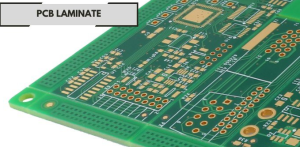
PCB Laminate
2: Historical Evolution of PCB Laminate Materials
The early days of PCB manufacturing revolved around basic phenolic resins and paper-based substrates. These were sufficient for simple consumer applications but lacked the resilience needed for industrial or high-performance domains. The development of glass-reinforced epoxy laminates marked a turning point. Among them, FR-4 became the de facto standard.
Initially, the focus was purely on cost-effective insulation and manufacturability. However, as circuit speeds increased and electronic products demanded higher reliability, PCB manufacturers began to explore new laminate compositions. This included polyimides for flexibility and heat resistance, PTFE-based laminates for RF applications, and cyanate ester blends for superior signal integrity.
One important realization that emerged over the decades is that laminate choice influences not only electrical performance but also downstream processes such as drilling, plating, and lamination yield. As such, materials are no longer selected just for their dielectric properties but also for their processing behavior and reliability under stress.
In my opinion, this evolution reflects a broader industry shift: we moved from designing for function to designing for sustainability, yield, and performance. In the era of 5G, IoT, and electric vehicles, the role of the PCB Laminate has become both foundational and strategic.
3: Key Properties of PCB Laminate Materials
When evaluating PCB laminate options, engineers must consider a spectrum of properties, often balancing trade-offs depending on application:
1. Dielectric Constant (Dk)
Lower Dk values are typically better for high-speed signal propagation. Most standard laminates offer Dk in the range of 4.2 to 4.8, while specialized RF materials go as low as 2.2.
2. Dissipation Factor (Df)
This defines energy loss within the material. High-frequency circuits require low Df to reduce signal attenuation. PTFE laminates, for example, offer excellent Df performance.
3. Thermal Conductivity
Important for heat dissipation in power electronics. While most FR-4 materials have low thermal conductivity (~0.3 W/m·K), ceramic-filled laminates can reach values above 1.0 W/m·K.
4. Glass Transition Temperature (Tg)
Tg marks the temperature above which the material becomes soft and rubbery. High-Tg laminates (>170°C) are critical for lead-free assembly processes and multilayer stack-ups.
5. Coefficient of Thermal Expansion (CTE)
CTE mismatch between copper and the laminate leads to delamination or pad lifting. Materials with low Z-axis CTE improve mechanical reliability.
In a practical sense, no single PCB laminate scores perfectly across all these metrics. The choice depends on the specific electrical, thermal, mechanical, and regulatory requirements. Design engineers must collaborate closely with material suppliers and fabricators to ensure alignment across the product lifecycle.
4: Types of PCB Laminate Based on Resin Composition
Different resins form the base of various PCB laminate materials, each tailored for specific use cases:
Epoxy Resins (FR-4)
By far the most commonly used material in general electronics. It offers a good mix of cost, mechanical strength, and electrical insulation. However, its performance is limited under high thermal or high-frequency environments.
Polyimide Laminates
These laminates excel in high-temperature applications and are used extensively in aerospace, automotive, and industrial applications. Their cost is higher, but so is their reliability in harsh environments.
PTFE-Based Laminates
Used in RF and microwave applications due to low Dk and Df values. PTFE (Teflon) offers excellent high-frequency performance but is challenging to process and requires specialized fabrication steps.
Cyanate Ester and PPE Blends
Engineered for high-speed digital designs, these materials offer a balance between high thermal stability and low signal loss. They’re becoming increasingly popular in data centers and telecom equipment.
Hydrocarbon Ceramic Laminates
Combining ceramic fillers with hydrocarbon resins, these materials provide a cost-effective alternative to PTFE while maintaining decent RF performance.
In my view, the diversification of PCB laminate materials reflects the diversification of electronics themselves—from smartphones to satellites. There’s no one-size-fits-all solution, and that complexity demands engineers remain informed and agile in their material choices.
5: PCB Laminate Materials and Their Electrical Performance
Electrical performance is among the most critical aspects when selecting PCB laminate materials, especially as electronic circuits become faster and more complex. The laminate’s dielectric properties, losses, and stability directly influence signal integrity, electromagnetic compatibility, and overall device reliability.
Dielectric Constant (Dk) and Its Impact
The dielectric constant, often denoted as Dk or εr, measures a material’s ability to store electrical energy in an electric field. It affects signal speed — higher Dk means slower signal propagation and increased capacitive coupling between traces.
Standard FR-4 laminates typically exhibit Dk values around 4.2 to 4.8 at 1 MHz, but this can vary with frequency and temperature. For high-speed digital circuits or RF/microwave applications, materials with lower Dk values (between 2.2 and 3.5) are preferred to minimize signal delay and cross-talk.
In practice, engineers must also consider the consistency of the Dk across the laminate sheet. Variations can cause impedance mismatches and degrade high-frequency signals. Leading manufacturers test laminates for Dk uniformity across the panel, which is crucial for multilayer and high-density designs.
Dissipation Factor (Df) and Signal Loss
The dissipation factor, or Df, quantifies the dielectric losses in the laminate. It represents the amount of energy dissipated as heat when an electric field is applied, affecting insertion loss in RF circuits and signal attenuation in high-speed data lines.
Low Df materials are essential for maintaining signal integrity over longer transmission distances and higher frequencies. For example, PTFE-based laminates can have Df values as low as 0.001, whereas typical FR-4 ranges from 0.02 to 0.03.
A laminate with a high Df will generate more heat and degrade signal quality, which may necessitate signal equalization or repeaters, increasing overall system cost and complexity.
Electrical Strength and Volume Resistivity
The electrical strength of a laminate measures its ability to withstand high voltages without breakdown, a critical factor in power electronics and high-voltage applications. Most laminates provide sufficient dielectric breakdown strength (20–50 kV/mm), but variations exist depending on resin type and filler content.
Volume resistivity determines how well the material insulates against leakage current. High volume resistivity (on the order of 10^14 ohm-cm or greater) is desirable to avoid leakage paths that can cause signal distortion or short circuits.
Stability Under Frequency and Temperature Variations
In real-world applications, PCB laminates face varying frequencies and temperatures. Electrical properties like Dk and Df tend to shift with these changes.
Advanced laminates are engineered to maintain stable electrical characteristics over a broad frequency range (from MHz to GHz) and temperature spectrum (-55°C to 150°C or higher). This stability is vital for aerospace, automotive, and telecommunications sectors, where reliability under harsh conditions is non-negotiable.
6: Thermal Considerations in PCB Laminate Selection
Thermal management is a fundamental aspect of PCB design and manufacturing, directly influenced by the choice of PCB laminate materials. As electronic devices continue to shrink in size while increasing in power density, laminates must effectively support heat dissipation to maintain circuit reliability and performance.
Importance of Thermal Properties in PCB Laminate
The key thermal properties that influence laminate performance include:
-
Glass Transition Temperature (Tg):
Tg is the temperature at which the laminate transitions from a rigid to a more rubbery state. Operating beyond Tg risks mechanical deformation and electrical instability. High Tg materials (>170°C) are essential for lead-free soldering processes and high-temperature applications. -
Decomposition Temperature (Td):
Td represents the temperature where the material begins to chemically degrade. Laminates with higher Td values (>300°C) offer better resilience during manufacturing processes like reflow soldering and wave soldering. -
Thermal Conductivity:
This measures the material’s ability to conduct heat away from components. Standard FR-4 materials have low thermal conductivity (~0.3 W/m·K), which can limit heat dissipation. Specialized ceramic-filled or metal-core laminates can improve this by factors of three or more. -
Coefficient of Thermal Expansion (CTE):
CTE quantifies how much the laminate expands or contracts with temperature changes. A mismatch between the laminate’s CTE and copper layers or components can cause mechanical stress, warping, and eventual failure.
Thermal Challenges in Modern PCB Manufacturing
As PCB complexity increases with multilayer stacks, fine pitch components, and embedded heat sources like power transistors and processors, managing thermal loads becomes more difficult.
For instance, in power electronics, hotspots can reach temperatures well above 150°C. A laminate that cannot withstand these conditions will delaminate or crack, leading to catastrophic failure.
Additionally, the transition to lead-free soldering requires laminates with higher Tg and Td to survive multiple thermal cycles without degradation.
Thermal Management Strategies Through Laminate Selection
Selecting the right PCB laminate for thermal performance can include:
-
Using high Tg materials such as polyimide-based laminates for applications requiring repeated thermal cycling.
-
Incorporating ceramic-filled laminates to boost thermal conductivity without compromising electrical insulation.
-
Employing metal-core laminates (aluminum or copper cores) in power-intensive applications to provide efficient heat spreading.
-
Optimizing laminate thickness and copper weights to balance mechanical strength and thermal dissipation.
7: PCB Laminate Materials and Signal Integrity
Signal integrity (SI) is a pivotal factor in modern high-speed electronic designs, and the choice of PCB laminate materials plays a foundational role in preserving it. Signal degradation, timing errors, and electromagnetic interference (EMI) can often be traced back to the electrical characteristics of the laminates used.
How Laminate Properties Affect Signal Integrity
-
Dielectric Constant (Dk) Consistency:
Variations in Dk lead to impedance mismatches along transmission lines, causing signal reflections, ringing, and jitter. Maintaining uniform Dk across the laminate sheet and multilayer stack is critical. -
Dissipation Factor (Df):
A higher Df increases signal loss and reduces the quality factor (Q) of resonant circuits, affecting high-frequency signal transmission. -
Surface Roughness of Copper Foil:
Though not part of the laminate substrate per se, copper surface texture combined with laminate properties affects conductor losses, especially at microwave frequencies. -
Moisture Absorption:
Laminates absorbing moisture exhibit increased dielectric losses and can shift Dk values, undermining SI.
Signal Integrity Challenges in High-Speed Designs
As data rates climb into the multi-gigabit range, even minor laminate imperfections can cause substantial SI problems:
-
Crosstalk:
Signal leakage between adjacent traces is exacerbated by dielectric constant variations and insufficient isolation. -
Insertion Loss:
Signal attenuation due to dielectric and conductor losses reduces effective signal amplitude and limits trace length. -
Skew and Timing Errors:
Impedance inconsistencies from laminate variation introduce signal delay differences, impairing timing synchronization.
Advanced PCB Laminate Materials for Improved SI
-
Low-Loss Materials:
Laminates engineered for low Df and stable Dk such as PTFE blends or specially formulated hydrocarbon resins improve signal transmission. -
High-Performance Glass Woven Fabrics:
Using finer weave glass cloth reduces signal scattering and dielectric variation. -
Prepreg and Core Compatibility:
Matching the prepreg resin system with the laminate core ensures uniform electrical properties throughout the multilayer stack.
8: Influence of PCB Laminate on Manufacturing Yield
Manufacturing yield is a critical metric in PCB production, and the choice of PCB laminate materials can significantly influence the rate of successful, defect-free boards. Understanding how laminate properties affect fabrication processes helps optimize yields and reduce costs.
Key Factors of PCB Laminate Affecting Manufacturing Yield
-
Dimensional Stability:
Laminates with stable thickness and minimal expansion/contraction under heat reduce misalignment during multilayer lamination and drilling. -
Glass Transition Temperature (Tg):
Materials with sufficiently high Tg withstand the thermal stresses of soldering and reflow without warping or delamination. -
Adhesion Properties:
Strong bonding between copper foil and laminate prevents copper lift and pad peeling during plating and assembly. -
Moisture Absorption:
High moisture uptake can cause “popcorning” defects during soldering due to rapid vaporization. -
Drill Hole Quality:
The laminate’s hardness and composition influence drill bit wear and hole wall smoothness, affecting plating and via reliability.
Common Yield Issues Related to PCB Laminates
-
Delamination:
Occurs when layers separate during thermal or mechanical stress, often due to improper resin flow or incompatible laminates. -
Copper Peel-Off:
Poor adhesion between copper and laminate leads to circuit failures and scrap. -
Warping and Bowing:
Caused by uneven thermal expansion or resin content, making assembly and testing difficult. -
Microcracking:
Resulting from CTE mismatch or mechanical stresses, leading to intermittent electrical failures.
Strategies to Improve Yield Through Laminate Selection
-
Choosing laminates with matched CTE to copper layers and components.
-
Selecting high-Tg laminates for lead-free and high-temperature processes.
-
Using low-moisture-absorption laminates and proper pre-baking before assembly.
-
Collaborating with fabricators to select laminates compatible with process parameters.
Conclusion
Choosing the right PCB Laminate is critical for PCB performance and reliability. Engineers must consider electrical, thermal, and mechanical requirements to optimize their designs. As technology evolves, new PCB Laminate innovations will continue to shape the future of electronics manufacturing.
The future of PCB laminates is bright and dynamic. As electronics continue to permeate every facet of life, laminates will evolve to meet increasingly complex demands. I anticipate materials that are lighter, stronger, more thermally efficient, and environmentally responsible, all while integrating new functionalities such as sensing and self-healing.
Selecting the right PCB laminate is both an art and a science, requiring a balance of technical knowledge, practical experience, and foresight. I hope this comprehensive guide provides valuable insights to empower informed decisions in PCB manufacturing, contributing to the success of next-generation electronic products.

- long board pcb
- Flexible PCBs
- Special PCB
- Express Printed Circuit Board
- Pcb Prototype
- LED PCB
- PCB
- Printed Circuit Board
- Pcb meaning
- Pcb manufacturer
- Rigid pcb board
- Rigid Flex PCB
 Quote
Quote
 E-mail