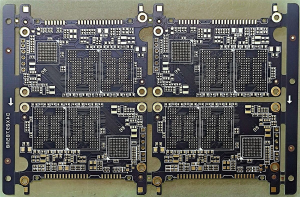
6. How to test pcb board, How Does In-Circuit Testing Work and What Can It Detect?
In-Circuit Testing (ICT) is one of the most powerful tools in high-volume PCB production. It uses a “bed-of-nails” fixture to make contact with test points across the board, checking components and nets without powering up the device.
But here’s the kicker — ICT doesn’t just test if components are present; it measures whether they perform correctly within expected tolerances. That’s a game-changer for automated quality control.
ICT can validate:
-
Passive component values (resistors, capacitors)
-
Semiconductor orientation and diode polarity
-
Presence of shorts or opens between nets
-
Basic logic functions for some ICs
While the fixture cost can be high (often thousands of dollars), it’s offset by lightning-fast test times—sometimes under 10 seconds per board.
Table: ICT Measurement Capabilities
| Component | Measured Property | Test Example |
|---|---|---|
| Resistor | Resistance | R1 = 1kΩ ± 5% |
| Capacitor | Capacitance, ESR | C2 = 10μF ± 10% |
| Diode | Forward voltage drop | Vf = 0.7V |
| Transistor | Gain, junction behavior | HFE = 150 |
| Net Connection | Continuity/isolation | Net1 ↔ Net2 = Open |
7. What Is Flying Probe Testing and When Should You Use It?
Flying Probe Testing (FPT) offers ICT-level accuracy without the need for a fixture. Instead of a bed-of-nails, FPT uses programmable robotic arms to place probes directly on pads, vias, and component leads.
Ready for the good part? FPT is ideal for low to medium volume runs and prototypes. You can reprogram it in minutes for a new layout, which is impossible with traditional ICT.
Use flying probe when:
-
You’re testing a small batch or development board
-
The board design changes frequently
-
Fixtures are too expensive or slow to build
FPT performs:
-
Continuity and isolation checks
-
Component value verification
-
Shorts and opens detection
-
Polarity and orientation checks
Table: Flying Probe vs ICT Comparison
| Factor | Flying Probe | In-Circuit Testing (ICT) |
|---|---|---|
| Setup Cost | Low | High (fixture required) |
| Programming Flexibility | High | Medium |
| Test Speed | Slower | Faster |
| Best Use Case | Prototypes, low-volume | Mass production |
8. How Is Functional Testing Used to Simulate Real-World Use?
Functional Testing (FCT) is the final step in PCB testing, simulating how the board behaves under actual operating conditions. It answers the question: “Does the board work the way it should when powered on?”
What’s the real story? FCT goes beyond checking individual components. It evaluates how those components work together in an integrated system. That’s why it’s essential in mission-critical electronics like medical monitors or flight control systems.
FCT covers:
-
Power rail verification
-
Signal output behavior
-
Communication interfaces (USB, UART, I²C, CAN)
-
Sensor response under stimuli
FCT often requires custom test jigs that replicate external peripherals and simulate inputs like buttons, load conditions, or environmental triggers.
Table: Functional Test Parameters
| Parameter Tested | Test Tool | Purpose |
|---|---|---|
| Output Voltage | Digital multimeter | Verify power regulator behavior |
| Signal Timing | Oscilloscope | Check clock, PWM, SPI signals |
| Bus Communication | Logic analyzer | Validate I²C, UART, CAN, USB |
| Sensor Output | Test software or fixture | Confirm input/output response |
9. How Can Continuity and Isolation Testing Catch Basic Faults?
Before jumping into advanced test systems, continuity and isolation tests are often the first sanity check. They ensure that what should be connected is connected—and what shouldn’t be isn’t.
But here’s the kicker — these basic tests catch many of the most catastrophic errors, like power-ground shorts, disconnected vias, or broken traces.
Continuity tests measure low-resistance paths across expected nets. Isolation tests ensure high resistance between unrelated nets to confirm there’s no leakage or shorting.
These tests are especially useful:
-
After PCB fabrication and before assembly
-
In high-voltage boards where insulation resistance is critical
-
As a fast go/no-go check post-assembly
Table: Continuity vs Isolation Testing
| Test Type | Pass Condition | Fail Indicator | Tools Used |
|---|---|---|---|
| Continuity Test | < 1Ω resistance | Open circuit (>1MΩ) | Multimeter, flying probe |
| Isolation Test | > 10MΩ resistance | Short or leakage (<1MΩ) | Megohmmeter, ICT |
10. What Role Does X-ray and 3D Inspection Play?
Some PCB problems hide below the surface — literally. That’s where X-ray and 3D inspection shine. These methods are essential for inspecting Ball Grid Arrays (BGAs), embedded components, and solder joints not visible to AOI or the human eye.
This is where it gets interesting — X-ray imaging not only reveals what’s hidden but can be layered into 3D tomographic data, letting you analyze solder ball shape, internal voids, and layer alignment.
These techniques are often used:
-
For boards with dense components like BGA, QFN
-
In aerospace and military PCBs where traceability is required
-
As part of failure analysis (RMA)
Table: X-ray Inspection Capabilities
| Inspection Type | What It Detects | Best For |
|---|---|---|
| 2D X-Ray | Solder voids, BGA bridging | Mid-range complexity boards |
| 3D X-Ray (CT Scan) | Internal cracks, layer shifting | High-reliability multilayer boards |
| Cross-section Analysis | Layer delamination | Failure root cause analysis |
11. How Do Signal Integrity Tests Work in High-Speed PCBs?
High-speed PCBs, used in routers, telecom, and automotive systems, face problems like signal reflection, attenuation, and crosstalk. Signal integrity testing ensures those problems don’t degrade board performance.
Ready for the good part? These tests are predictive and diagnostic. Tools like Time Domain Reflectometry (TDR) and Vector Network Analyzers (VNA) help detect mismatched impedances or degraded traces long before a signal ever leaves the board.
Engineers analyze:
-
Rise/fall time distortion
-
Eye diagrams for digital communication
-
Reflection coefficients and impedance
These tests are crucial for compliance with standards like USB 3.0, PCIe, and DDR4.
Table: Signal Integrity Testing Tools
| Tool | Function | Use Case |
|---|---|---|
| TDR | Detects impedance mismatch | Differential pair analysis |
| VNA | Measures S-parameters | RF and high-speed data links |
| Oscilloscope | Captures waveform shape | Clock and data edge timing |
| Eye Diagram Tools | Visualizes data jitter | High-speed communication buses |
12. What Testing Strategies Are Used for Multilayer PCBs?
Multilayer PCBs introduce added complexity—more interconnections, more chances for layer misalignment, and harder-to-access test points. Standard testing often falls short.
But here’s the kicker — testing multilayer PCBs isn’t just harder, it’s smarter. You need specialized techniques to see what’s going on deep inside.
Common multilayer strategies include:
-
TDR for impedance and layer matching
-
X-ray for via alignment
-
Flying probe to access internal vias
-
Microsectioning for destructive root-cause analysis
Design-for-Test (DFT) becomes essential here. Including test vias and breakout traces during layout can simplify access later.
Table: Multilayer PCB Test Techniques
| Challenge | Testing Method | Why It’s Effective |
|---|---|---|
| Inner-layer shorts/opens | Flying probe, TDR | Reaches buried nets |
| Impedance verification | TDR, simulation | Validates high-speed routing |
| BGA via alignment | X-ray, microsectioning | Confirms drill alignment |
13. How Should You Develop a Robust Test Strategy?
A robust test strategy balances cost, time, and coverage. It considers the product’s life cycle stage, industry requirements, and expected volume.
Here’s where it gets practical — no one method covers it all. Your best move is to layer methods: early-stage inspection + mid-level electrical testing + final functional validation.
Start by asking:
-
Is this a prototype, pilot run, or full production?
-
What are the quality and reliability expectations?
-
What failures would be most damaging (costly recalls, brand impact)?
Table: Test Strategy Planner
| Stage | Recommended Methods | Why It’s Ideal |
|---|---|---|
| Prototyping | Visual, flying probe, FCT | Flexible, detailed feedback |
| Low-volume | AOI, continuity, flying probe | Fast ROI, reprogrammable |
| High-volume | AOI, ICT, FCT | Fast, automated, consistent |
| Mission-critical | X-ray, 3D AOI, environmental | Maximum reliability |
14. What Are the Most Common Testing Mistakes and How to Avoid Them?
Mistakes in PCB testing can undo all the effort put into design and fabrication. Worse, they often come to light only when customers start returning failed units.
This is where it gets interesting — most testing failures are avoidable. They stem from skipped steps, poor documentation, or over-reliance on a single method.
Top mistakes include:
-
Skipping test points during layout
-
Using outdated golden board images in AOI
-
Overlooking false negatives in ICT
-
Failing to calibrate fixtures regularly
How to fix it?
-
Involve test engineers early in PCB design (DFT)
-
Establish maintenance protocols for test equipment
-
Regularly update test software with new board revisions
Table: Testing Pitfalls and Fixes
| Mistake | Consequence | Prevention Strategy |
|---|---|---|
| Skipping test point design | Limited test coverage | Use DFT rules in layout |
| Outdated test fixtures | False failures or misses | Regular calibration |
| Incomplete inspection logs | Missed trends, poor traceability | Digital test data logging |
15. How Can You Future-Proof Your PCB Testing Process?
Technology evolves. So should your testing. Future-proofing your process ensures it scales with new components, new speeds, and new customer demands.
What’s the real story? Companies that invest in flexible, data-driven, and software-integrated testing are staying ahead of the curve. They’re ready for 5G, AI-driven analytics, and smart factories.
Future-ready steps include:
-
Integrating Design-for-Test (DFT) from the start
-
Using cloud-based test data for analytics
-
Employing modular test jigs adaptable to multiple designs
-
Applying machine learning for predictive defect detection
Table: Future-Proofing Tactics
| Upgrade Area | Future Benefit | Example |
|---|---|---|
| DFT-Ready Layouts | Easier test coverage, automation | Built-in test vias, pads |
| Smart Test Systems | Adaptive pass/fail decision logic | AI-inspection AOI systems |
| Cloud Integration | Historical defect analysis | PowerBI, AWS, Azure dashboards |
| Reusable Fixtures | Cost-effective for similar boards | Modular pogo-pin bed systems |
Conclusion
Mastering PCB testing isn’t just about catching errors — it’s about building confidence into every board you ship. From early-stage inspections to advanced functional testing, every method plays a role in achieving zero-defect production. In high-stakes B2B environments, this commitment to testing sets you apart as a true partner, not just a supplier. The right mix of techniques, guided by smart strategy and powered by modern tools, ensures that your PCBs don’t just pass — they excel.
How to test pcb board, FAQ
Q1: What is PCB testing?
PCB testing is the process of checking printed circuit boards for defects, ensuring they perform correctly under specified conditions.
Q2: How does in-circuit testing work?
In-circuit testing uses electrical probes to measure and verify individual components and connections on an unpowered PCB.
Q3: What’s the difference between AOI and flying probe testing?
AOI is an optical inspection for surface-level defects, while flying probe testing electrically verifies connections and components without a fixed fixture.
Q4: How do I choose the best PCB testing method?
It depends on factors like production volume, complexity, speed, and budget. Combining methods often yields better coverage.
Q5: Why is functional testing important?
Functional testing ensures the PCB operates correctly under real-world conditions, validating both hardware and software interfaces.

 Quote
Quote
 E-mail