Thermocouple Connector PCB: Design, Applications, and Key Considerations
Thermocouple connectors are essential components in industrial and scientific applications for temperature measurement. These connectors interface with thermocouples, which are temperature sensors that generate voltage based on temperature differences between two dissimilar metals. In many cases, a printed circuit board (PCB) is used to integrate the thermocouple with the broader measurement system. The design of thermocouple connector PCBs must ensure accurate temperature readings, reliable signal transmission, and durable performance in harsh environments. This article explores the design considerations, applications, and best practices for thermocouple connector PCBs, providing valuable insights for engineers and manufacturers.
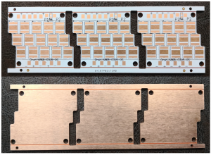
Thermocouple Connector PCB
What is a Thermocouple Connector PCB?
A thermocouple connector PCB is a specialized printed circuit board designed to connect thermocouples to measurement and control systems. Thermocouples consist of two dissimilar metal wires joined at one end to form a junction, which produces a small voltage proportional to the temperature difference between the junction and the reference point. The thermocouple connector PCB provides the interface for connecting the thermocouple to a larger system, which could include amplifiers, data acquisition systems, or microcontrollers.
The PCB helps facilitate the transmission of the thermocouple signal to the control system and often incorporates additional features such as signal conditioning, amplification, and isolation. For reliable performance, the PCB must maintain the integrity of the signal while ensuring long-term durability in environments subject to temperature fluctuations, vibration, and electrical noise.

Thermoelectric Separation PCB Board
The Role of Thermocouple Connector PCBs
Thermocouple connector PCBs perform several crucial roles in temperature measurement systems:
- Signal Integrity: Ensuring that the voltage generated by the thermocouple is transmitted accurately to the measurement system without distortion or interference.
- Connection Point: Providing a reliable and secure connection between the thermocouple and the measurement system.
- Temperature Management: Helping maintain the integrity of the thermocouple signal by incorporating features like isolation and compensation for temperature effects.
- Protection and Durability: Offering mechanical protection to the thermocouple wiring and system components in demanding environments.
Key Design Considerations for Thermocouple Connector PCBs
Designing thermocouple connector PCBs requires careful attention to various factors to ensure the accuracy, reliability, and robustness of the final product. Below are the key considerations:
1. Material Selection
Material selection plays a significant role in the design of thermocouple connector PCBs. The choice of materials must take into account factors such as thermal conductivity, electrical conductivity, mechanical strength, and durability in high-temperature environments. Common materials used in thermocouple connector PCBs include:
- FR4: The most commonly used material for standard PCBs. It offers good electrical insulation and mechanical properties at a reasonable cost. However, it may not be suitable for very high-temperature applications.
- High-Temperature Materials: For applications that require high temperature resistance, materials such as polyimide or ceramic-based PCBs are often used. These materials can withstand temperatures well above the limits of standard FR4 boards.
- Copper: As the primary conductor in PCBs, copper must be carefully chosen for its thickness and plating to ensure that the thermocouple signal is transmitted efficiently without significant losses.
2. Thermocouple Type and Compatibility
Thermocouples are available in various types, such as Type K, Type J, Type T, and others, each having distinct characteristics and voltage-temperature relationships. It is crucial to design the thermocouple connector PCB with the specific type of thermocouple in mind. The PCB should be compatible with the thermocouple’s material and ensure that the temperature readings are accurately captured.
- Type K Thermocouples: These are the most common and have a wide temperature range, making them suitable for many industrial applications.
- Type T Thermocouples: Known for their accuracy in low-temperature applications, these thermocouples are often used in cryogenic systems and food safety measurements.
- Type J Thermocouples: These thermocouples are used in environments where moderate temperature ranges are required.
Matching the correct thermocouple type to the PCB design is essential for ensuring that the temperature signal is accurately interpreted.
3. Signal Conditioning and Amplification
Thermocouples generate very small voltages that need to be amplified and conditioned before being processed by the measurement system. Thermocouple connector PCBs often incorporate signal conditioning circuitry, such as amplifiers, filters, and analog-to-digital converters (ADCs), to ensure that the signal is both amplified and stable. Some key aspects of signal conditioning include:
- Amplification: Thermocouple signals are typically in the millivolt range, so they need to be amplified to a level that can be accurately processed by microcontrollers or other electronics.
- Filtering: Signal noise can distort the voltage generated by the thermocouple, so filters are used to remove high-frequency noise or interference from nearby electrical equipment.
- Cold Junction Compensation (CJC): The reference junction of a thermocouple is usually at a different temperature than the measurement junction. Cold junction compensation is used to correct for the difference in temperature, ensuring accurate readings.
4. Temperature Compensation and Isolation
Temperature compensation is crucial for thermocouple connectors, as the temperature of the PCB itself can affect the signal accuracy. For high-precision applications, the PCB design should incorporate temperature compensation techniques to account for the self-heating effects and environmental temperature fluctuations.
Isolation is also an important consideration, especially when thermocouples are used in environments with high electrical noise or where there is a risk of electrical interference. Isolating the thermocouple signal from other electronic components helps maintain the integrity of the measurement and prevents potential damage to the system.
5. Mechanical Protection and Durability
Thermocouple connector PCBs are often used in industrial environments where mechanical stress, vibration, and extreme temperatures are common. Therefore, it is crucial to design the PCB with sufficient protection to ensure its longevity and reliable performance. This may include:
- Encapsulation or Potting: Encapsulating the PCB in a protective resin or potting material helps protect it from moisture, dust, and mechanical damage.
- Shock and Vibration Resistance: For applications involving heavy machinery or vehicles, the PCB should be designed to withstand shock and vibration, preventing failure or degradation over time.
- High-Temperature Tolerance: For applications in high-temperature environments, the PCB should be able to operate within the required temperature range without degradation of performance.
Applications of Thermocouple Connector PCBs
Thermocouple connector PCBs are used in a variety of industries where accurate temperature measurement and control are essential. Key applications include:
1. Industrial Temperature Control Systems
Thermocouples are widely used in industrial applications to monitor and control the temperature of processes such as metal casting, chemical manufacturing, and power generation. Thermocouple connector PCBs interface with the thermocouples to ensure accurate temperature readings that can be used to regulate equipment or trigger alarms if the temperature exceeds safe limits.
2. Automotive and Aerospace
In automotive and aerospace applications, thermocouples are used to measure the temperature of engines, exhaust systems, and other critical components. Thermocouple connector PCBs ensure that the temperature signals are accurately transmitted to the control systems for monitoring performance and safety.
3. Consumer Electronics
Thermocouples are used in consumer electronics for temperature monitoring in devices such as ovens, refrigerators, and air conditioners. In these applications, thermocouple connector PCBs help interface with the thermocouple and ensure that the temperature is accurately measured to maintain optimal performance and energy efficiency.
4. Medical Devices
Thermocouples are used in medical applications, including temperature monitoring in diagnostic equipment, sterilizers, and incubators. Thermocouple connector PCBs provide a reliable interface between the thermocouple and the measurement system, ensuring precise and consistent temperature readings.
Best Practices for Designing Thermocouple Connector PCBs
To ensure the best performance and reliability of thermocouple connector PCBs, consider the following best practices:
1. Ensure Proper Shielding and Grounding
Proper shielding and grounding are essential to prevent electromagnetic interference (EMI) from affecting the thermocouple signal. Use shielded enclosures and ground planes to isolate the signal and maintain accuracy.
2. Optimize Trace Routing and Layout
When designing the PCB layout, ensure that traces carrying the thermocouple signals are routed away from high-power components or noisy signals. Minimize the length of these traces to reduce noise and potential voltage drops.
3. Implement Robust Testing and Calibration
Before deployment, thoroughly test and calibrate thermocouple connector PCBs to ensure accurate temperature readings. Use temperature-controlled chambers or reference thermocouples for precise calibration.
4. Design for Manufacturing (DFM)
Ensure that the PCB design is optimized for manufacturability, minimizing the risk of defects during the fabrication process. Adhering to standard design practices and working closely with manufacturers can help avoid common design issues.
Conclusion
Thermocouple connector PCBs play a crucial role in enabling accurate and reliable temperature measurements in a wide range of industrial, automotive, medical, and consumer electronics applications. The design of these PCBs requires careful consideration of materials, thermocouple types, signal conditioning, and temperature compensation. By adhering to best practices in design, testing, and manufacturing, engineers can ensure that thermocouple connector PCBs deliver optimal performance and durability in challenging environments.

- long board pcb
- Flexible PCBs
- Special PCB
- Express Printed Circuit Board
- Pcb Prototype
- LED PCB
- PCB
- Printed Circuit Board
- Pcb meaning
- Pcb manufacturer
- Rigid pcb board
- Rigid Flex PCB
 Quote
Quote
 E-mail