Thermal Clad PCB: A Comprehensive Guide to Heat-Resistant Circuit Boards
Introduction
In modern electronic design, thermal management plays a crucial role in ensuring the reliability and longevity of components. One of the most effective solutions for heat dissipation in electronic circuits is the thermal clad PCB. These printed circuit boards (PCBs) integrate a metal-based layer that efficiently dissipates heat, making them ideal for high-power and high-temperature applications.
This article explores thermal clad PCBs, their structure, benefits, applications, and key design considerations.
thermal clad pcb, Thermoelectric Separation PCB Board
What is a Thermal Clad PCB?
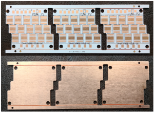
A thermal clad PCB, also known as a metal core PCB (MCPCB), is a type of printed circuit board that features a thermally conductive dielectric layer and a metal substrate. This structure significantly enhances heat dissipation, reducing overheating risks in high-power electronic devices.
Basic Structure of a Thermal Clad PCB
- Copper Layer (Circuit Layer) – The top layer consists of copper traces that carry electrical signals.
- Thermally Conductive Dielectric Layer – A crucial insulating layer with high thermal conductivity that transfers heat from the circuit layer to the metal core.
- Metal Substrate (Base Layer) – Typically made of aluminum, copper, or stainless steel, this layer dissipates heat effectively and provides mechanical strength.
Key Benefits of Thermal Clad PCBs
1. Enhanced Heat Dissipation
Compared to traditional FR4 PCBs, thermal clad PCBs efficiently transfer heat away from heat-sensitive components, preventing thermal failure.
2. Increased Reliability
By reducing heat buildup, these PCBs extend the lifespan of electronic components, reducing the risk of malfunction and failure.
3. Higher Power Handling Capability
Due to their excellent thermal performance, thermal clad PCBs can support higher power levels without excessive temperature rise.
4. Improved Mechanical Strength
The metal base provides stability and durability, making thermal clad PCBs resistant to mechanical stress and environmental conditions.
5. Compact and Lightweight Design
With better thermal performance, designers can use smaller heat sinks, reducing the overall weight and size of the product.
Applications of Thermal Clad PCBs
Thermal clad PCBs are widely used in applications that require efficient heat dissipation, including:
1. LED Lighting Systems
- Used in high-power LEDs to prevent overheating.
- Improves LED lifespan and efficiency.
- Common in street lighting, automotive LEDs, and display backlighting.
2. Power Electronics
- Ideal for power converters, inverters, and power regulators.
- Enhances performance in renewable energy systems like solar inverters.
3. Automotive Industry
- Used in engine control units (ECUs), power modules, and sensor systems.
- Withstands harsh conditions such as high temperatures and vibrations.
4. Industrial and Automation Equipment
- Employed in motor drivers, industrial control systems, and high-power machinery.
- Ensures reliable operation in demanding environments.
5. Consumer Electronics
- Used in power amplifiers, chargers, and gaming consoles.
- Prevents overheating in compact devices.
Material Selection for Thermal Clad PCBs
1. Metal Core (Base Layer)
- Aluminum – The most commonly used metal due to its balance between cost, thermal performance, and weight.
- Copper – Offers superior thermal conductivity but is more expensive and heavier.
- Stainless Steel – Provides mechanical strength but lower thermal conductivity.
2. Dielectric Layer (Insulation Layer)
- The dielectric layer is a thermally conductive material that electrically isolates the circuit layer from the metal core.
- Common materials include ceramic-filled epoxy and polyimide, designed for high thermal conductivity.
3. Copper Layer (Circuit Layer)
- Typically ranges from 1 oz to 6 oz in thickness.
- Designed for electrical conductivity and mechanical durability.
Thermal Clad PCB Manufacturing Process
Step 1: Material Preparation
- Selection of metal base, dielectric layer, and copper foil.
- Cleaning and surface treatment to ensure proper adhesion.
Step 2: Circuit Layer Formation
- Copper foil is laminated onto the dielectric layer.
- Photolithography and etching are used to define circuit traces.
Step 3: Dielectric Layer Application
- A thermally conductive dielectric layer is applied between the copper and metal base.
- This layer determines the PCB’s heat dissipation efficiency.
Step 4: Metal Base Integration
- The metal core is laminated to the dielectric layer.
- Additional surface treatments (such as anodizing) are applied for durability.
Step 5: Drilling and Finishing
- Holes and vias are drilled for component mounting.
- Solder mask and silkscreen printing are applied.
Step 6: Testing and Quality Control
- Electrical and thermal conductivity tests are performed.
- Thermal cycling tests to ensure performance under temperature variations.
Key Design Considerations for Thermal Clad PCBs
1. Thermal Management Optimization
- Proper copper trace width selection to enhance heat dissipation.
- Placement of thermal vias for improved heat transfer.
- Integration of heat sinks or external cooling solutions where necessary.
2. Component Placement
- Heat-generating components should be placed close to the metal core.
- Components with low thermal resistance should be arranged to maximize heat dissipation.
3. Electrical Isolation and Safety
- Ensuring the dielectric layer thickness meets safety requirements.
- Proper clearance between traces to prevent electrical shorts.
4. Mechanical and Environmental Factors
- Selecting a metal core material based on operating environment.
- Coating or surface treatment for protection against oxidation and corrosion.
Future Trends in Thermal Clad PCBs
1. Advanced Thermal Materials
- The development of high-performance ceramics and composite dielectrics to improve heat transfer efficiency.
2. Integration with Smart Electronics
- Combining thermal clad PCBs with IoT for real-time temperature monitoring.
3. Miniaturization and High-Density Integration
- Advanced HDI (High-Density Interconnect) techniques to support compact electronic designs.
4. Green and Sustainable PCB Manufacturing
- Adoption of lead-free and environmentally friendly materials to reduce the ecological impact.
Conclusion
Thermal clad PCBs provide an essential solution for heat dissipation in high-power and high-temperature applications. By integrating a metal core, thermally conductive dielectric, and optimized circuit layers, these PCBs enhance the reliability and efficiency of electronic devices.
With the increasing demand for power electronics, LED lighting, automotive systems, and industrial automation, thermal clad PCBs continue to evolve. Advances in materials, manufacturing processes, and integration techniques will further improve their performance and sustainability.
Choosing the right thermal clad PCB design ensures better thermal management, improved product lifespan, and enhanced overall performance in various electronic applications.

- long board pcb
- Flexible PCBs
- Special PCB
- Express Printed Circuit Board
- Pcb Prototype
- LED PCB
- PCB
- Printed Circuit Board
- Pcb meaning
- Pcb manufacturer
- Rigid pcb board
- Rigid Flex PCB
 Quote
Quote
 E-mail