1. Introduction to Testing Circuit Boards with a Multimeter
A multimeter is an indispensable tool in electronics, combining several measurement functions into one instrument. When testing circuit boards, it facilitates the identification of faults such as short circuits, open circuits, and component failures. Understanding how to effectively use a multimeter is crucial for anyone involved in electronic diagnostics and repairs.
Testing a circuit board with a multimeter is a fundamental skill in electronics, enabling technicians and engineers to diagnose and troubleshoot various issues effectively. A multimeter, being a versatile instrument, allows for the measurement of voltage, current, and resistance, among other parameters. This comprehensive guide delves into the methodologies and best practices for utilizing a multimeter to test circuit boards, ensuring accurate diagnostics and maintenance.
1.1 Importance of Testing circuit board with a multimeter
- Fault Diagnosis: Quickly identify defective components or connections.
- Preventive Maintenance: Regular testing can preempt potential failures.
- Quality Assurance: Ensures that circuit boards meet design specifications.
1.2 Overview of Multimeter Functions
- Voltage Measurement (Voltmeter): Determines potential difference between two points.
- Current Measurement (Ammeter): Measures the flow of electric charge.
- Resistance Measurement (Ohmmeter): Assesses the opposition to current flow.
- Continuity Testing: Checks if a circuit path is complete.
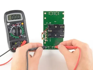
Testing circuit board with a multimeter
2. Preparing to Test Circuit Boards with a Multimeter
Before initiating tests, proper preparation is crucial to ensure safety and accuracy.
2.1 Safety Precautions
- De-energize the Circuit: Always disconnect power before testing to prevent electric shock and equipment damage.
- Discharge Capacitors: Capacitors can retain charge; ensure they are fully discharged.
- Personal Protective Equipment (PPE): Use insulated gloves and safety glasses when necessary.
2.2 Tools and Equipment Needed
- Digital Multimeter: Preferred for its accuracy and additional features.
- Test Leads and Probes: Ensure they are in good condition and rated for the expected measurements.
- Circuit Schematic: A reference to understand the design and expected values.
2.3 Understanding the Circuit Board Layout
Familiarize yourself with the board’s layout, including:
- Component Placement: Identify resistors, capacitors, diodes, etc.
- Trace Pathways: Understand how connections are routed.
- Test Points: Locate designated points for measurement.
3. Setting Up the Multimeter for Testing Circuit Boards
Proper setup of the multimeter is essential for obtaining accurate readings.
3.1 Selecting the Appropriate Measurement Mode
- Voltage Mode: For measuring potential difference.
- Current Mode: For assessing current flow; ensure probes are connected to the correct terminals.
- Resistance Mode: For checking resistance values.
- Continuity Mode: Often indicated by a diode symbol; emits a beep when continuity is present.
3.2 Choosing the Correct Measurement Range
- Auto-Ranging Multimeters: Automatically select the appropriate range.
- Manual-Ranging Multimeters: Manually set the range; start from the highest setting to prevent overload.
3.3 Calibrating the Multimeter
Regular calibration ensures measurement accuracy. Follow the manufacturer’s guidelines or use known reference values to verify performance.
4. Testing for Continuity on Circuit Boards with a Multimeter
Continuity testing verifies that electrical paths are unbroken.
4.1 Purpose of Continuity Testing
- Identify Open Circuits: Detect breaks in connections.
- Verify Connections: Ensure that solder joints and traces are intact.
4.2 Performing a Continuity Test
- Set Multimeter to Continuity Mode: Look for the diode symbol or a sound icon.
- Test the Probes: Touch them together; a beep confirms functionality.
- Place Probes on Test Points: Connect to the two points you wish to test.
- Interpret Results: A continuous beep indicates an unbroken path; silence suggests an open circuit.
4.3 Applications of Continuity Testing
- Tracing PCB Paths: Follow the flow of connections.
- Checking Switches and Relays: Ensure they open and close circuits properly.
- Verifying Fuses: Confirm they are intact and functional.
5. Measuring Resistance on Circuit Boards with a Multimeter
Resistance measurement helps in verifying component values and detecting issues like short circuits.
5.1 Importance of Measuring Resistance
- Component Verification: Ensure resistors and other components have correct values.
- Detecting Faults: Identify shorts or unexpected resistance levels.
5.2 Steps to Measure Resistance
- Power Off the Circuit: Prevents inaccurate readings and potential damage.
- Set Multimeter to Resistance Mode: Indicated by the Ω symbol.
- Place Probes Across the Component: Ensure good contact without touching other parts.
- Read the Display: Compare the measured value to the expected resistance.
5.3 Factors Affecting Resistance Measurements
- Parallel Paths: Other components may influence readings.
- Temperature: Resistance can change with temperature fluctuations.
- Component Tolerances: Manufacturing variations can cause slight differences.
6. Measuring Voltage on Circuit Boards with a Multimeter
Voltage measurements are crucial for assessing the operational status of a circuit.
6.1 Types of Voltage Measurements
- DC Voltage: Common in battery-powered and digital circuits.
- AC Voltage: Found in mains-powered and analog circuits.
6.2 Procedure for Measuring Voltage
- Power On the Circuit: Voltage measurements require an active circuit.
- Set Multimeter to Voltage Mode: Choose DC or AC as needed.
- Connect Probes: Place the black probe on the ground/reference point and the red probe on the test point.
- Observe Polarity: For DC measurements, ensure correct probe placement to avoid negative readings.
- Read the Measurement: Compare against expected values to assess functionality.
6.3 Common Voltage Measurement Points
- Power Supply Outputs: Verify correct voltage levels.
- Across Components: Check voltage drops to assess component operation.
- Signal Lines: Ensure signals are within expected voltage ranges.
7. Measuring Current on Circuit Boards with a Multimeter
Assessing current flow is vital for understanding circuit performance.
7.1 Understanding Current Measurement
- Series Connection: The multimeter must be placed in series with the circuit.
- Burden Voltage: The multimeter introduces a small voltage drop; consider this in sensitive circuits.
7.2 Steps to Measure Current
- Power Off the Circuit: Ensure safety before modifying connections.
- Set Multimeter to Current Mode: Select the appropriate current range.
- Break the Circuit: Create a point where the multimeter can be inserted in series.
- Connect Probes in Series: Ensure secure and correct connections.
- Power On the Circuit: Observe the current reading.
- Power Off and Reconnect: After measurement, restore the circuit to its original state.
7.3 Precautions When Measuring Current
- Avoid Overloading: Ensure the expected current does not exceed the multimeter’s rating.
- Secure Connections: Loose probes can cause arcing or inaccurate readings.
- Minimize Measurement Time: Prolonged measurements can affect circuit performance due to burden voltage.
8. Testing Diodes and Transistors on Circuit Boards with a Multimeter
Semiconductor components such as diodes and transistors play a crucial role in electronic circuits. Proper testing ensures they function correctly and helps in diagnosing faulty components.
8.1 Testing Diodes on a Circuit Board with a Multimeter
Diodes allow current to flow in only one direction, making them essential for rectification and protection circuits.
8.1.1 Steps to Test a Diode
- Set the Multimeter to Diode Mode: This mode typically displays a diode symbol.
- Identify the Anode and Cathode: The cathode is usually marked with a band.
- Measure the Forward Voltage:
- Place the red probe on the anode and the black probe on the cathode.
- A functioning silicon diode should show a voltage drop of approximately 0.6–0.7V.
- A Schottky diode may show a lower voltage drop (0.2–0.3V).
- Measure the Reverse Bias:
- Reverse the probes.
- The multimeter should display “OL” (open circuit), indicating no conduction.
8.1.2 Common Issues Identified by Diode Testing
- Shorted Diode: If the multimeter shows near-zero resistance in both directions, the diode is likely shorted.
- Open Diode: If the multimeter shows “OL” in both directions, the diode is likely damaged.
8.2 Testing Transistors on a Circuit Board with a Multimeter
Transistors are essential for amplification and switching applications. They can be tested using the diode mode of a multimeter.
8.2.1 Identifying Transistor Terminals
Transistors have three terminals:
- Base (B)
- Collector (C)
- Emitter (E)
8.2.2 Testing an NPN Transistor
- Set the Multimeter to Diode Mode.
- Measure the Base-Emitter Junction:
- Place the red probe on the base and the black probe on the emitter.
- A good transistor should show a forward voltage drop (typically 0.6–0.7V).
- Measure the Base-Collector Junction:
- Place the red probe on the base and the black probe on the collector.
- The multimeter should again show a forward voltage drop of 0.6–0.7V.
- Check Reverse Bias:
- Reverse the probes for both tests.
- The multimeter should read “OL,” indicating no conduction.
8.2.3 Testing a PNP Transistor
- Repeat the steps above, but reverse the multimeter probes.
- The black probe should be on the base, and the red probe should be on the collector/emitter.
8.2.4 Common Transistor Faults
- Short Circuit: Both junctions show low resistance in both directions.
- Open Circuit: One or both junctions show “OL” in forward bias.
9. Diagnosing Common PCB Faults with a Multimeter
A multimeter can identify various issues on a circuit board. Below are some of the most frequent faults and their testing methods.
9.1 Identifying Open Circuits
- Set the Multimeter to Continuity Mode.
- Place the Probes Across a Suspected Broken Connection.
- If There Is No Beep, the connection is likely broken.
9.2 Detecting Short Circuits
- Set the Multimeter to Resistance Mode.
- Measure Resistance Between Two Points That Should Be Isolated.
- A Low Resistance Reading (Near 0Ω) suggests a short circuit.
9.3 Checking Power Supply Issues
- Measure Voltage Across the Power Rails.
- Compare Readings With Expected Values.
- If Voltage is Too Low or Missing, check the power source, connectors, and regulators.
9.4 Diagnosing Faulty Capacitors
- Set the Multimeter to Capacitance Mode (if available).
- Place the Probes Across the Capacitor Terminals.
- Compare Measured Capacitance With the Rated Value.
- If the Capacitance is Too Low or “OL,” the capacitor may be faulty.
10. Best Practices for Testing Circuit Boards with a Multimeter
Following best practices ensures safe and accurate testing.
10.1 Ensuring Accurate Measurements
- Use Proper Probe Contact: Ensure firm and stable contact.
- Avoid Interference: Keep test leads away from electromagnetic noise sources.
- Zero the Multimeter: Before resistance testing, touch the probes together and note any offset.
10.2 Preventing Damage to Components
- Avoid Excessive Test Voltage: Some sensitive components can be damaged by the multimeter’s internal voltage.
- Minimize Prolonged Contact: Holding probes in place too long can heat up components.
10.3 Regular Multimeter Maintenance
- Check the Battery: A weak battery can lead to inaccurate readings.
- Inspect Test Leads: Replace damaged or worn-out probes.
- Calibrate Regularly: Ensure the multimeter is functioning correctly.
11. Advanced Troubleshooting Techniques Using a Multimeter
For complex PCBs, advanced troubleshooting techniques may be necessary.
11.1 In-Circuit vs. Out-of-Circuit Testing
- In-Circuit Testing: Allows for quick diagnostics but can be affected by surrounding components.
- Out-of-Circuit Testing: More accurate but requires desoldering the component.
11.2 Using a Multimeter with Other Diagnostic Tools
- Oscilloscope: Provides waveform analysis.
- LCR Meter: Measures inductance, capacitance, and resistance more accurately.
- Logic Analyzer: Diagnoses digital signal issues.
12. Conclusion: The Importance of Testing Circuit Boards with a Multimeter
Testing circuit board with a multimeter is a crucial skill for electronics professionals and hobbyists alike. By systematically measuring voltage, resistance, continuity, and component performance, users can effectively diagnose and repair circuit issues.
A well-maintained and properly calibrated multimeter ensures accurate readings, while careful handling of circuit boards prevents damage. Following best practices and integrating additional diagnostic tools enhances the reliability and efficiency of PCB troubleshooting.
By mastering multimeter testing techniques, engineers and technicians can extend the life of electronic devices, reduce repair costs, and maintain high-performance standards in PCB manufacturing and maintenance.
In modern electronics, the ability to effectively test circuit boards with a multimeter is essential for ensuring functionality, reliability, and longevity. Whether troubleshooting faults in consumer electronics, industrial equipment, or advanced communication systems, a multimeter remains one of the most versatile and fundamental diagnostic tools. By understanding its different functions, users can systematically identify problems, prevent potential failures, and improve the overall performance of printed circuit boards (PCBs).
12.1 The Role of Testing Circuit Boards with a Multimeter
One of the most significant advantages of regularly testing circuit boards with a multimeter is preventative maintenance. Rather than waiting for a failure to occur, routine diagnostics help detect early warning signs of degradation in electrical components.
- Preventing Major Failures: Identifying issues such as voltage fluctuations, high resistance connections, or abnormal power consumption can prevent a minor issue from escalating into a major failure.
- Reducing Downtime in Critical Systems: In industrial applications, unexpected equipment failure can result in costly production delays. Regular PCB testing ensures that critical systems remain operational.
- Extending Component Lifespan: Many electrical components degrade over time due to heat, stress, or environmental conditions. Periodic multimeter checks can help identify components that need replacement before they cause circuit failure.
By integrating multimeter-based diagnostics into routine maintenance schedules, engineers and technicians can improve the longevity and reliability of electronic systems.
12.2 The Evolution of Multimeter Testing in Electronics
While multimeters have been in use for decades, their capabilities have evolved significantly with technological advancements. Today’s multimeters offer a range of sophisticated features that go beyond basic voltage and resistance measurements.
- Auto-ranging Functionality: Modern digital multimeters automatically select the correct measurement range, eliminating the need for manual adjustments.
- Data Logging Capabilities: Some advanced multimeters can store test results, allowing for trend analysis and historical comparisons.
- Wireless Connectivity: Certain high-end models offer Bluetooth connectivity, enabling remote monitoring and integration with diagnostic software.
- Expanded Testing Capabilities: Features such as capacitance, frequency, and temperature measurement allow for a more comprehensive circuit board evaluation.
As multimeters continue to evolve, their role in PCB testing and troubleshooting will only become more critical, offering more precise and efficient diagnostics.
12.3 Common Challenges in Testing Circuit Boards with a Multimeter
While multimeter testing is an essential tool for diagnosing PCB issues, it is not without challenges. Engineers and technicians often encounter the following obstacles:
1. Misinterpretation of Readings
- Incorrect probe placement or misunderstanding of multimeter settings can lead to false conclusions about circuit integrity.
- Solution: Ensure proper training and understanding of electrical principles before performing PCB tests.
2. Measuring in Complex Multi-Layer PCBs
- As circuit boards become more compact and multi-layered, accessing test points becomes increasingly difficult.
- Solution: Utilize test points and vias designed specifically for diagnostics, and supplement with advanced tools like oscilloscopes when necessary.
3. Testing Live Circuits
- Measuring high-voltage PCBs or sensitive digital circuits requires caution, as incorrect probe placement can damage components or cause safety hazards.
- Solution: Follow proper safety protocols and use insulated probes when testing high-voltage circuits.
Overcoming these challenges through best practices and continuous learning ensures accurate and reliable PCB diagnostics.
12.4 The Future of Testing Circuit Boards with a Multimeter
As electronics continue to advance, the demand for faster, more accurate, and automated testing solutions is increasing. While multimeters remain indispensable, new testing methodologies are emerging to complement their capabilities.
1. Integration with AI-Based Diagnostics
- Artificial intelligence (AI) is being integrated into PCB testing to analyze patterns and predict failures based on historical data.
- Future multimeters may include AI-powered features that automatically diagnose PCB issues and suggest repair solutions.
2. Automated Optical and Electrical Testing
- Advanced automated optical inspection (AOI) systems and automated test equipment (ATE) are being increasingly used for high-volume PCB manufacturing.
- These technologies work alongside multimeters to provide comprehensive fault detection.
3. Enhanced PCB Design for Easier Testing
- Modern PCB designs incorporate built-in test points and diagnostic features that make multimeter testing more efficient.
- Future advancements may lead to self-testing circuit boards that can automatically detect and report faults.
As these technologies develop, multimeter-based PCB testing will remain a core part of electronic diagnostics, but it will be increasingly complemented by automated and AI-driven tools.
12.5 Final Thoughts: Mastering Multimeter Testing for PCB Reliability
The ability to test circuit boards with a multimeter is a fundamental skill that benefits engineers, technicians, and electronics enthusiasts alike. Whether identifying voltage irregularities, diagnosing component failures, or preventing short circuits, multimeter testing ensures circuit boards operate at peak efficiency.
By mastering this skill and integrating best practices, professionals can:
- Enhance product reliability in PCB manufacturing.
- Reduce repair costs in electronic maintenance.
- Improve safety and efficiency in industrial applications.
While emerging technologies will continue to enhance PCB testing methods, multimeters will remain an essential tool for years to come. The key to success lies in continuous learning, practice, and adaptation to new testing technologies, ensuring that circuit boards remain functional, reliable, and high-performing in an ever-evolving electronic landscape.

- long board pcb
- Flexible PCBs
- Special PCB
- Express Printed Circuit Board
- Pcb Prototype
- LED PCB
- PCB
- Printed Circuit Board
- Pcb meaning
- Pcb manufacturer
- Rigid pcb board
- Rigid Flex PCB
 Quote
Quote
 E-mail