Inner Layer Exposure in PCB Manufacturing
Introduction
Inner layer exposure is a critical step in the printed circuit board (PCB) manufacturing process, where the photoresist-coated inner layers are exposed to ultraviolet (UV) light to define the circuit patterns. This process ensures that the copper traces are accurately formed, allowing for precise circuit connectivity and performance.
In multilayer PCB production, achieving high precision and uniformity in inner layer exposure is essential. The accuracy of this process directly impacts the quality of etching, registration, and layer alignment. This article will cover the purpose, key processes, equipment, quality control measures, and challenges involved in inner layer exposure in PCB manufacturing.
Inner Layer Exposure
Purpose of Inner Layer Exposure
The inner layer exposure process serves multiple essential functions:
- Pattern Transfer: Defines the circuit pathways by selectively exposing photoresist to UV light.
- High Precision Imaging: Ensures fine-line circuit features are accurately formed.
- Layer Alignment Accuracy: Enables precise layer-to-layer registration in multilayer PCBs.
- Defect Reduction: Minimizes common issues such as underexposure, overexposure, or misalignment.
- Improved Circuit Reliability: Enhances electrical performance and manufacturing yield.
Proper execution of the inner layer exposure step ensures that the PCB meets design specifications and industry standards.
Key Processes in Inner Layer Exposure
The inner layer exposure process consists of several critical steps to achieve precise and defect-free circuit patterns:
1. Preparation and Cleaning
Before exposure, the PCB panel undergoes thorough cleaning to remove dust, oxidation, and contaminants that could interfere with imaging.
- Cleaning Methods:
- Chemical cleaning
- Mechanical scrubbing
- High-pressure air blowing
- Outcome: Ensures a smooth, contaminant-free surface for better photoresist adhesion.
2. Photoresist Coating
A layer of photosensitive material (photoresist) is applied to the copper surface to allow selective exposure.
- Types of Photoresist:
- Dry Film Photoresist (DFR): Laminated onto the surface using heat and pressure.
- Liquid Photoresist (LPR): Applied via spray or spin coating for high-resolution imaging.
- Outcome: A uniformly coated copper surface, ready for UV exposure.
3. Alignment and Registration
Proper alignment of the photomask (negative or positive film) and PCB panel is crucial for precise circuit formation.
- Methods of Alignment:
- Optical alignment using fiducial markers
- Automated registration systems for precision positioning
- Outcome: Ensures that circuit patterns are accurately aligned for layer stacking.
4. UV Light Exposure
The photoresist is exposed to UV light through a photomask that contains the circuit pattern.
- Types of Exposure Techniques:
- Contact Exposure: The photomask is directly placed on the PCB for high precision.
- Projection Exposure: Uses a lens system for non-contact imaging with reduced contamination risk.
- Direct Laser Imaging (DLI): Eliminates the need for photomasks by directly writing the pattern using a laser.
- Outcome: Selective hardening of photoresist in exposed areas while unexposed areas remain soluble.
5. Post-Exposure Baking
The exposed PCB undergoes a soft baking process to stabilize the photoresist and improve development quality.
- Baking Parameters:
- Temperature: 80°C to 100°C
- Time: 2 to 5 minutes
- Outcome: Reduces defects and enhances adhesion before development.
6. Development Process
The unexposed (soluble) photoresist is removed using a developer solution, revealing the circuit pattern.
- Types of Developers:
- Sodium carbonate for alkaline photoresists
- Solvent-based developers for specific resist types
- Outcome: A well-defined circuit pattern ready for the etching process.
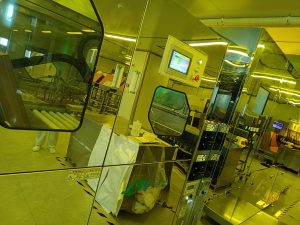
Equipment Used in Inner Layer Exposure
1. Auto Cleaning Systems
- Ensures contaminant-free surfaces for photoresist application.
2. Photoresist Laminators
- Applies uniform dry film or liquid photoresist layers.
3. Automatic Alignment and Registration Systems
- Provides precision positioning of photomasks and PCB panels.
4. UV Exposure Units
- Uses high-intensity UV light sources to harden photoresist in patterned areas.
- Common systems include:
- Contact Printers (for direct exposure)
- Laser Direct Imaging (LDI) Systems (for maskless exposure)
5. Development Chambers
- Removes unexposed photoresist using automated chemical spraying systems.
6. Post-Exposure Baking Ovens
- Ensures photoresist stability and adhesion enhancement.
Quality Control Measures
To ensure high precision and reliability, manufacturers implement strict quality control during inner layer exposure:
1. Alignment Inspection
- Uses automated optical alignment systems to detect misregistration.
2. Exposure Dose Calibration
- Monitors UV intensity and exposure time to prevent underexposure or overexposure.
3. Photoresist Thickness Measurement
- Ensures uniform application using profilometers and film thickness gauges.
4. Defect Analysis
- Employs automated optical inspection (AOI) to identify issues such as:
- Overdevelopment (loss of fine features)
- Underdevelopment (incomplete pattern transfer)
- Dust or particle contamination
5. Cross-Sectional Microscopy
- Examines layer structure to verify proper resist adhesion and pattern accuracy.
Challenges and Solutions in Inner Layer Exposure
1. Misalignment Issues
- Cause: Poor registration between layers.
- Solution: Use advanced optical alignment systems with fiducial markers.
2. Overexposure or Underexposure
- Cause: Inconsistent UV light intensity.
- Solution: Regularly calibrate exposure equipment and monitor UV levels.
3. Photoresist Defects
- Cause: Uneven lamination or contamination.
- Solution: Implement strict surface preparation and lamination quality control.
4. Underdevelopment or Overdevelopment
- Cause: Improper developer concentration or time.
- Solution: Optimize development parameters and maintain chemical quality.
Conclusion
Inner layer exposure is a critical PCB manufacturing step that ensures accurate circuit pattern transfer for multilayer boards. By employing advanced exposure techniques, precision alignment, and rigorous quality control measures, manufacturers can achieve high reliability, fine-line accuracy, and defect-free PCBs.
As technology advances, innovations such as direct laser imaging (DLI) and automated exposure systems continue to improve the precision and efficiency of inner layer exposure, supporting the growing demands of high-performance electronic applications.
our linkedin sqpcb.com

- long board pcb
- Flexible PCBs
- Special PCB
- Express Printed Circuit Board
- Pcb Prototype
- LED PCB
- PCB
- Printed Circuit Board
- Pcb meaning
- Pcb manufacturer
- Rigid pcb board
- Rigid Flex PCB
 Quote
Quote
 E-mail