Heavy copper PCBs are gaining traction in industries where high power, heat management, and durability are mission-critical. This article dives deep into everything professionals need to know about heavy copper PCBs—from what they are and why they matter, to how they’re designed, manufactured, and applied across high-demand sectors. Whether you’re sourcing for automotive, energy, or industrial applications, this comprehensive guide covers all technical, financial, and practical aspects. Let’s explore the world of heavy copper PCBs and discover how they can future-proof your power electronics systems.
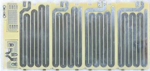
Heavy Copper PCB
1. Introduction to Heavy Copper PCBs
So, what’s the deal with heavy copper PCBs? They’re not your average printed circuit boards. Instead, they’re designed with copper layers that exceed 3 oz/ft², making them the go-to solution for high-current and high-thermal applications.
Heavy copper PCBs are used in sectors where performance can’t be compromised. Think electric vehicles, solar inverters, industrial drives, and military equipment. Why? Because these boards handle stress like a champ. They support high current, resist thermal damage, and provide structural strength in punishing environments.
But here’s the kicker… While standard PCBs usually cap out at 1 oz copper layers, heavy copper boards may go all the way to 10 oz or more! This allows for superior power distribution and thermal conductivity, critical for long-term reliability.
Manufacturers love them because they reduce the need for external heat sinks. Designers love them for compact power integration. Engineers love them for reliability. No wonder they’re booming in advanced tech ecosystems.
Let’s set the stage with a quick overview of their defining traits.
| Copper Weight | Thickness (mm) | Application Example |
|---|---|---|
| 1 oz/ft² | 0.035 mm | Consumer electronics |
| 3 oz/ft² | 0.105 mm | Power converters |
| 5 oz/ft² | 0.175 mm | Automotive chargers |
| 8 oz/ft² | 0.280 mm | Military-grade power systems |
2. Understanding Copper Weight in PCBs
Before diving deeper, let’s clarify one thing: copper “weight” doesn’t mean how much it tips the scale. It refers to the thickness of the copper spread over one square foot of the PCB—measured in ounces per square foot (oz/ft²).
But what’s the real story? Here it is—this measurement is crucial because it directly impacts the board’s current-carrying capability and heat management. One ounce of copper per square foot equals about 35 microns in thickness. But in a heavy copper PCB, you’re looking at 3 oz (105 microns) and beyond.
Here’s how copper thickness breaks down:
| Copper Classification | Thickness (µm) | Typical Use |
|---|---|---|
| Standard | 35 µm | Low-power electronics |
| Medium | 70 µm | Consumer and light industrial |
| Heavy | 105–210 µm | Automotive, power, industrial |
| Extreme | >210 µm | Military, aerospace, high current |
As copper weight increases, trace width and spacing must be carefully designed to avoid overheating or failure. For example, a 5 oz trace can carry 20–30 amps depending on width and environment.
And guess what? Designers can stack different copper weights on inner and outer layers to balance performance and cost. It’s all about matching your copper to the job’s electrical and mechanical needs.
3. Key Benefits of Heavy Copper PCBs
Let’s cut to the chase—why go heavy?
First, there’s the current-carrying capacity. These boards are beasts when it comes to conducting high amperage. That’s crucial in applications like power converters, chargers, and energy storage systems.
Next, we have thermal performance. Ready for the good part? Thicker copper spreads heat more efficiently, minimizing hotspots and preventing component damage. This often means you can ditch bulky heatsinks or fans.
There’s also mechanical strength. With more copper mass, the board becomes more rugged and resistant to warping, vibration, and environmental stress.
And here’s where it gets interesting… Heavy copper PCBs also enable compact design. Instead of spreading power across multiple layers, you can route high-current traces closer together, reducing board size without compromising power integrity.
Let’s look at how the benefits stack up.
| Benefit | Impact | Example Use |
|---|---|---|
| Higher current capacity | Reduces overheating risk | EV battery BMS |
| Better thermal management | Longer component life | Inverter modules |
| Structural integrity | Prevents delamination | Aerospace controls |
| Compact layouts | Space-saving designs | Industrial IoT controllers |
4. Common Applications of Heavy Copper PCBs
You might be wondering—where do these PCBs actually shine?
Let’s start with automotive electronics. In electric vehicles, battery systems and inverters demand boards that can carry massive current without failure. Heavy copper makes that possible.
Then there’s renewable energy. Solar power inverters and wind turbine controllers use them for heat management and long-term reliability. These systems can’t afford downtime.
In power electronics, heavy copper enables high-efficiency DC-DC converters, uninterruptible power supplies (UPS), and motor controllers. It’s all about power density and resilience.
Still curious? Military and aerospace sectors rely on these boards for radar, power distribution, and mission-critical systems. Here, failure is not an option.
Let’s break down a few more applications.
| Application Area | Why Heavy Copper? | Specific Use |
|---|---|---|
| Automotive | High current paths | EV fast chargers |
| Renewable Energy | Efficient heat removal | Solar inverter PCBs |
| Industrial Power | Durability and power | Motor drivers |
| Aerospace | Long lifecycle | Flight control power |
5. Materials Used in Heavy Copper PCBs
Not all base materials are created equal—especially when carrying lots of current.
FR4, the workhorse of PCBs, can still be used for moderate heavy copper builds, but it struggles when things heat up. That’s why many designers shift to high-Tg laminates, ceramics, or even metal-core PCBs for more extreme builds.
But wait, there’s more… The type of copper foil also matters. Rolled annealed (RA) copper is flexible and ideal for stress-bearing applications, while electrodeposited (ED) copper is more affordable for standard heavy builds.
Let’s compare the most common materials.
| Material | Strengths | Limitations |
|---|---|---|
| FR4 | Cost-effective, widely available | Limited heat resistance |
| High-Tg Epoxy | Better thermal stability | Higher cost |
| Ceramic | Excellent for heat dissipation | Brittle, expensive |
| Metal-core (MCPCB) | Top thermal performance | Complex manufacturing |
Add to that specialty dielectric films or prepregs, and you’ve got a complex material stack tailored for durability, conductivity, and thermal performance.
6. Heavy Copper PCB Layer Structures
Layering matters—a lot.
You’ll often see single-layer heavy copper boards in simple power modules. But in advanced applications, multilayer PCBs dominate. These stack-ups allow for precise routing of signal, ground, and power planes with optimized copper distribution.
But here’s the twist… In heavy copper multilayers, the inner copper layers might not be as thick as the outer ones. Why? To manage cost and thermal expansion while still providing robust performance.
Thermal vias also play a critical role—acting like vertical chimneys to carry heat from hot components through the board.
Typical stack-up might look like this:
| Layer | Function | Copper Weight |
|---|---|---|
| Top Layer | High-current traces | 5 oz |
| Prepreg | Insulation | – |
| Inner Layer 1 | Signal routing | 2 oz |
| Core | Structural layer | – |
| Inner Layer 2 | Ground plane | 2 oz |
| Prepreg | – | – |
| Bottom Layer | Power return | 5 oz |
Each layer contributes to the overall thermal, electrical, and mechanical performance.
7. Manufacturing Process of Heavy Copper PCBs
Here’s where things get tricky.
Unlike standard PCBs, heavy copper boards need specialized plating and etching processes. That’s because thick copper doesn’t etch as easily—it tends to undercut or cause jagged trace walls.
Enter differential etching and step plating. Step plating builds up copper in stages, allowing precise control over thickness. These techniques require tighter process tolerances and more aggressive quality control.
But what’s the real story? Manufacturing heavy copper PCBs is slower and costlier. Specialized tools and chemical solutions are used, and the plating bath must be closely monitored to avoid uneven copper distribution.
Here’s a simplified workflow:
| Step | Description |
|---|---|
| Material selection | Choose base + foil |
| Lamination | Stack and press layers |
| Step plating | Layer-by-layer copper buildup |
| Imaging & etching | Trace patterns created |
| Drilling & via filling | Through-holes created |
| Surface finish | ENIG, OSP, or HASL |
| Final testing | Electrical + visual inspection |
8. Design Guidelines for Heavy Copper Circuits
Designing a heavy copper PCB isn’t just about making traces thicker.
You’ve got to rethink trace width, spacing, and via diameter. A 5 oz copper trace might need to be 5–10 mm wide to carry 25 amps safely. That takes space—and impacts your layout.
But here’s the kicker… Using too-small vias can result in overheating and delamination. Instead, opt for plated through-holes or via stitching for high-current paths.
Balance is key—between thermal management, signal integrity, and mechanical durability.
Design guidelines often follow this logic:
| Parameter | Minimum Value for 5 oz Copper |
|---|---|
| Trace Width (25A) | 6–10 mm |
| Via Hole Diameter | ≥0.5 mm |
| Copper Clearance | ≥0.5 mm |
| Thermal Via Count | ≥10 per hotspot |
Using IPC-2221 standards, thermal simulation tools, and collaboration with your PCB manufacturer will help you avoid critical design errors.
9. Thermal Management in Heavy Copper PCBs
Thermal management is the beating heart of heavy copper PCB design. Why? Because high-current circuits generate intense heat—and if you don’t control it, failure follows fast.
But this is where it gets interesting… Heavy copper PCBs inherently help dissipate heat due to the mass of copper, but smart thermal design multiplies that advantage. Key techniques include thermal vias, heat-spreading planes, and high-Tg laminates.
Designers often add copper pours to act as heat sinks, connecting them via vias to internal planes. These act as thermal expressways, carrying heat away from sensitive components.
Let’s not forget thermal simulation. Using tools like ANSYS or SolidWorks PCB can pinpoint hotspots before the board is even fabricated.
Check out common thermal strategies:
| Technique | Function | Typical Use |
|---|---|---|
| Thermal Vias | Vertical heat transfer | Power MOSFETs, drivers |
| Copper Planes | Horizontal dissipation | Ground/power layers |
| Heat Sinks | External cooling | High-power regulators |
| High-Tg Materials | Withstand heat cycling | Industrial drives |
The result? A PCB that not only survives the heat—but thrives in it.
10. Cost Factors and Pricing Insights
Let’s talk money.
Heavy copper PCBs aren’t cheap—but they’re worth it. You’re paying for more copper, thicker plating, slower etching, and more robust materials. But here’s the kicker… these costs are often offset by reduced need for external cooling and longer product lifespan.
The pricing isn’t linear either. Moving from 1 oz to 3 oz might only raise costs by 20%, but jumping from 3 oz to 6 oz could double your cost. Why? Because production time, scrap rate, and material usage rise exponentially.
Want to control cost? Stick to these tips:
● Limit copper weight to what’s absolutely necessary
● Use hybrid layers (e.g., 5 oz outer, 2 oz inner)
● Reduce layer count where possible
● Avoid excessive via fill or blind vias unless essential
Here’s a pricing matrix:
| Copper Weight | Cost Increase vs. Standard | Notes |
|---|---|---|
| 1 oz | Base cost | Entry-level boards |
| 3 oz | +20% | Common heavy design |
| 5 oz | +50–60% | High power, mid-size |
| 8 oz | +100%+ | Military/industrial only |
Budget-conscious? Collaborate with your manufacturer early in the design phase.
11. Common Challenges and Design Pitfalls
Designing with heavy copper sounds great—but it’s not without hurdles.
First, etching difficulties. Thick copper layers require slower, controlled etching. If not done properly, you’ll get sloped sidewalls or undercut traces. That impacts conductivity and reliability.
Then there’s warping and bowing. This is especially problematic in large-format boards or when copper isn’t symmetrically balanced between layers.
Here’s the real story… Heavy copper increases stress on the substrate during lamination and cooling. If your layer stack isn’t well thought out, the board can curl like a potato chip.
Other common mistakes?
● Overlooking thermal via density
● Undersizing trace width for current load
● Skipping design for manufacturability (DFM) reviews
Let’s summarize typical issues and fixes:
| Issue | Cause | Solution |
|---|---|---|
| Over-etching | Inadequate process control | Step plating, differential etch |
| Bowing | Uneven copper distribution | Symmetrical stack-up |
| Thermal runaway | Poor via planning | Add thermal vias near hotspots |
| Cost overruns | Overdesign | Collaborate early with fabricator |
Want fewer headaches? Work closely with experienced manufacturers who know heavy copper nuances.
12. Testing and Quality Assurance
Here’s the non-negotiable part—testing.
Why? Because these boards are often mission-critical. If they fail, it’s not just costly—it’s dangerous. That’s why heavy copper PCBs undergo stringent testing and inspection protocols.
The essentials? Automated Optical Inspection (AOI), Flying Probe or Bed of Nails Electrical Testing, X-ray analysis, and Cross-section micrography.
But wait—there’s more. IPC-6012 Class 2 or Class 3 compliance is often required, especially for medical, aerospace, and defense electronics.
Testing helps detect:
● Copper thickness irregularities
● Poor solderability
● Internal delamination
● Via cracking or poor plating
Here’s a typical QA checklist:
| Test Type | What It Verifies | Frequency |
|---|---|---|
| AOI | Surface trace integrity | 100% boards |
| Electrical Test | Open/short detection | 100% boards |
| X-ray | Inner layer alignment, BGA quality | Per batch |
| Micro-section | Copper thickness, via walls | Random sampling |
And remember—don’t just test post-production. Include design validation steps to catch issues early.
13. Comparing Heavy Copper with Standard Copper PCBs
Wondering if heavy copper is truly worth it?
Let’s put them side-by-side. Standard copper PCBs work great for low to medium power applications. But when you hit the high current zone—heavy copper wins, hands down.
Here’s the difference. Standard PCBs are lighter, cheaper, and easier to manufacture. Heavy copper PCBs are thicker, pricier, and more rugged.
But here’s the real story… You’re not choosing one over the other randomly. Your application requirements drive the decision. If your board must carry more than 5 amps continuously, heavy copper is often the right answer.
Here’s a breakdown:
| Feature | Standard PCB | Heavy Copper PCB |
|---|---|---|
| Copper Weight | 1 oz | 3–10 oz |
| Current Capacity | Up to 5A | 10–50A+ |
| Cost | Low | High |
| Durability | Moderate | Excellent |
| Heat Dissipation | Basic | Superior |
The result? You trade cost for performance—but when it matters, there’s no substitute.
14. Choosing a Reliable Heavy Copper PCB Manufacturer
Here’s where many companies drop the ball.
You need a fabricator who’s not just familiar—but specialized in heavy copper PCB manufacturing. The processes are different, the tools are different, and the risks are higher.
So what should you look for?
● Proven experience with 5 oz+ builds
● In-house plating and etching expertise
● Certifications like ISO9001, UL, IPC Class 3
● Willingness to do DFM reviews and thermal simulations
But wait, there’s more. Ask for test reports, copper thickness validation, and real customer case studies. A top-tier supplier will gladly provide them.
Checklist to qualify vendors:
| Criteria | Why It Matters |
|---|---|
| Min 3 years heavy copper experience | Ensures process maturity |
| Plating tolerance ±10% | Precision matters |
| In-house testing lab | Faster turnaround |
| Engineering support | Better collaboration |
Make sure you’re not just buying a product—you’re partnering for performance.
15. Future Trends in Heavy Copper PCB Technology
Where’s this tech heading?
With the rise of electric vehicles, energy storage, and industrial automation, demand is skyrocketing for high-power, heat-resistant PCBs. That means innovation is coming fast.
AI-driven simulation tools are emerging for better thermal modeling. Flexible heavy copper circuits are also being explored for robotic and wearable power systems.
And here’s where it gets interesting… Hybrid stack-ups combining rigid copper layers with flexible substrates are enabling compact, dynamic power electronics in drones and compact power packs.
The industry is also pushing for more sustainable plating methods, using fewer hazardous chemicals and improving recyclability.
Trends to watch:
| Trend | Impact |
|---|---|
| EV infrastructure | Surge in high-current PCBs |
| Smart grids | Decentralized power needs |
| Flexible heavy copper | Robotics, wearables |
| AI modeling | Faster thermal prototyping |
Ready to stay competitive? Keeping up with these trends is your ticket to future-proof circuit design.
Conclusion
Heavy copper PCBs are not just thicker boards—they’re the backbone of modern power electronics. From unmatched current handling to incredible thermal control, they offer performance where it counts. But designing and producing them requires careful planning, specialized materials, and the right manufacturing partner. By understanding their benefits, challenges, and best practices, you’re equipped to deliver reliability in even the harshest environments. Choose wisely, design smart, and let your PCBs carry the heavy load with confidence.
FAQ Section
Q1: What is a heavy copper PCB?
A heavy copper PCB is a printed circuit board with copper layers thicker than 3 oz/ft², built to carry high current and withstand high temperatures in power-demanding applications.
Q2: How does copper thickness impact PCB performance?
Increased copper thickness enhances current capacity, improves heat dissipation, and boosts mechanical strength, making the board more durable in demanding environments.
Q3: Can heavy copper PCBs be used in multilayer designs?
Yes, heavy copper can be integrated into multilayer boards, typically with thicker copper on outer layers for heat and current, and standard copper inside to manage cost.
Q4: Are heavy copper PCBs suitable for high-frequency applications?
Not usually. While they excel in power handling, their thickness can complicate impedance control, making them less suitable for high-frequency RF designs.
Q5: What industries benefit most from heavy copper PCBs?
Industries such as automotive (EV), renewable energy, aerospace, military, and industrial automation rely on heavy copper PCBs for their durability and power capabilities.

- long board pcb
- Flexible PCBs
- Special PCB
- Express Printed Circuit Board
- Pcb Prototype
- LED PCB
- PCB
- Printed Circuit Board
- Pcb meaning
- Pcb manufacturer
- Rigid pcb board
- Rigid Flex PCB
 Quote
Quote
 E-mail