1. Introduction to Metal Core PCB Technology
Metal Core PCB (MCPCB) technology represents a pivotal evolution in the printed circuit board industry, specifically designed to address the increasing thermal challenges in modern electronics. Unlike traditional FR-4 boards, a Metal Core PCB integrates a base layer of metal—commonly aluminum, copper, or an alloy—which serves as a heat-spreading foundation. This design ensures that excessive heat generated by high-power components is efficiently dissipated, prolonging the lifespan of the electronics and ensuring consistent performance.
The growing adoption of Metal Core PCB technology is driven by the proliferation of high-brightness LEDs, high-frequency power converters, and compact industrial systems. As device miniaturization continues, heat density rises, making the use of thermally conductive substrates a necessity rather than a luxury.
In my view, the real breakthrough of Metal Core PCB lies not merely in its ability to manage heat but in its ability to integrate mechanical strength and dimensional stability with electrical performance. This combination allows engineers to push power and density limits without sacrificing reliability — a balancing act that was far more difficult with purely dielectric-based boards.
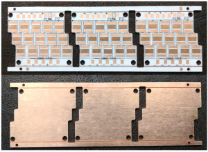
Metal Core PCB
2. Structure and Composition of Metal Core PCB
A Metal Core PCB is composed of three primary layers:
-
Metal Base Layer – This is typically aluminum (most common due to cost-effectiveness), copper (superior thermal conductivity), or a special alloy. The choice of base metal has a direct influence on heat dissipation capability and mechanical rigidity.
-
Dielectric Layer – A thermally conductive but electrically insulating material separates the metal base from the copper circuit layer. This layer’s thermal conductivity value is critical in determining overall heat transfer efficiency.
-
Copper Circuit Layer – The etched copper traces carry electrical signals. Copper thickness in Metal Core PCB designs is often greater than in standard FR-4 boards to accommodate higher current loads.
Some advanced Metal Core PCB designs also incorporate multi-layer stack-ups, integrating multiple signal layers above the dielectric. This allows the integration of more complex circuits while retaining the thermal advantages of the metal core.
3. Advantages of Metal Core PCB in Thermal Management
The primary advantage of a Metal Core PCB lies in its exceptional thermal conductivity. While a typical FR-4 board offers thermal conductivity in the range of 0.3–0.4 W/m·K, aluminum-based Metal Core PCBs can achieve 1–3 W/m·K or higher. Copper-based cores can exceed 400 W/m·K in thermal conductivity, making them suitable for extremely high-power applications.
Key benefits include:
-
Efficient Heat Dissipation: By transferring heat away from sensitive components, Metal Core PCB reduces the risk of thermal runaway.
-
Improved Component Reliability: Stable operating temperatures extend the mean time between failures (MTBF).
-
Reduced Need for Additional Cooling Hardware: In some designs, the Metal Core PCB itself acts as the heatsink, eliminating bulky fans or secondary heat spreaders.
-
Enhanced Mechanical Strength: The metal core resists bending and vibration, important for automotive and industrial environments.
From my perspective, the most overlooked advantage is that thermal stability allows tighter component tolerances and more stable electrical characteristics. In precision electronics, even small temperature fluctuations can cause drift in component values; Metal Core PCB mitigates this risk significantly.
4. Impact of Metal Core PCB on Electrical Performance
While Metal Core PCB technology is primarily adopted for its superior thermal management, its influence on electrical performance should not be underestimated. The mechanical and thermal stability of a Metal Core PCB allows for tighter control over impedance, reduced dielectric loss, and more predictable high-frequency signal transmission.
Electrical advantages include:
-
Stable Dielectric Properties: The thermally conductive dielectric in a Metal Core PCB is engineered to maintain a consistent dielectric constant (Dk) over a wide temperature range. This stability benefits RF and high-speed digital applications.
-
Reduced Signal Degradation: Heat-induced expansion in standard FR-4 can cause micro-cracks or via barrel distortion. Metal Core PCB structures mitigate these issues, preserving signal integrity.
-
Lower Electromagnetic Interference (EMI): A grounded metal core can act as an EMI shield, especially in sensitive mixed-signal circuits.
-
Improved Current Carrying Capacity: The thicker copper layers typically used in Metal Core PCB designs allow for higher current flow without excessive resistive heating.
From my own engineering perspective, the synergy between thermal and electrical benefits is where Metal Core PCB really shines. A design that maintains consistent electrical characteristics while controlling temperature provides far more predictable performance over a product’s lifetime.
5. Material Selection in Metal Core PCB Manufacturing
Choosing the right materials for a Metal Core PCB is not simply a matter of picking the cheapest aluminum plate or the thickest copper foil. Each layer — from the core to the dielectric to the copper traces — must be selected to balance cost, performance, and manufacturing feasibility.
Metal Core Layer Options:
-
Aluminum: Lightweight, cost-effective, corrosion-resistant. Best for LED lighting and mid-range power electronics.
-
Copper: Superior thermal conductivity, but heavier and more expensive. Ideal for military, aerospace, or extreme high-power applications.
-
Alloys (e.g., Aluminum-Silicon): Tailored thermal expansion properties to match specific semiconductor packaging requirements.
Dielectric Layer Considerations:
-
Thermal conductivity values typically range from 1 W/m·K to over 5 W/m·K.
-
Must also have high dielectric breakdown voltage to ensure electrical isolation.
-
Low thermal resistance is critical for rapid heat transfer.
Copper Circuit Layer:
-
Thickness can range from 1 oz to over 6 oz copper, depending on current-carrying requirements.
-
Surface finish choices — HASL, ENIG, immersion silver — impact solderability and corrosion resistance.
In my view, one of the most common design oversights in Metal Core PCB projects is failing to match the thermal expansion coefficients (CTE) of all layers. When mismatched, thermal cycling can cause delamination — a failure mode that negates the thermal advantages of the design.
6. Fabrication Process of Metal Core PCB
Manufacturing a Metal Core PCB is more complex than producing a conventional FR-4 PCB. The process must accommodate thicker base layers, specialized drilling, and more robust lamination steps.
General process steps include:
-
Metal Preparation: The core surface is cleaned, mechanically brushed, and sometimes chemically treated to improve adhesion.
-
Dielectric Lamination: The thermally conductive dielectric is applied to the metal core using high-pressure lamination techniques.
-
Copper Lamination: Copper foil is bonded on top of the dielectric to form the conductive layer.
-
Imaging and Etching: The circuit pattern is photo-imaged and etched, just like in traditional PCB fabrication.
-
Drilling and Plating: Holes are drilled through the copper and dielectric (but often not through the entire metal core unless designed for it) and plated for electrical interconnection.
-
Solder Mask and Surface Finish: Protective solder mask layers and desired surface finishes (e.g., ENIG, HASL) are applied.
-
Routing and Profiling: The board is cut to its final shape, often using CNC milling due to the metal base.
-
Testing: Electrical and thermal performance is verified before shipping.
A personal note from my production experience — tool wear is significantly higher when processing Metal Core PCB materials, especially copper cores. This means that PCB manufacturers must invest in specialized drill bits and milling tools to maintain precision.
7. Applications of Metal Core PCB in Power Electronics
In the realm of power electronics, Metal Core PCB technology has become a cornerstone for reliable high-power system design. Power electronics often involve rapid switching, high current loads, and dense component layouts, all of which generate significant heat. Without effective thermal management, components like MOSFETs, IGBTs, and power diodes can suffer from premature failure.
Key application areas:
-
DC-DC Converters: Metal Core PCB allows higher power density by keeping switching devices cooler.
-
Motor Control Systems: Drives for industrial motors and electric vehicles benefit from vibration-resistant, heat-tolerant designs.
-
Inverters for Renewable Energy: Solar and wind power inverters generate significant thermal loads; Metal Core PCB extends their service life.
-
Uninterruptible Power Supplies (UPS): Long-term reliability under continuous load is improved when heat is efficiently managed.
From my perspective, the real value of Metal Core PCB in power electronics is not only reducing cooling system costs but also enabling designs where passive cooling is sufficient, which reduces maintenance needs.
8. Applications of Metal Core PCB in LED Lighting Systems
LED lighting has been one of the largest growth drivers for Metal Core PCB adoption over the past decade. High-brightness LEDs convert a large portion of electrical energy into heat, and excessive temperatures can cause lumen depreciation and color shift.
Why Metal Core PCB is ideal for LED lighting:
-
Thermal Path Efficiency: Transfers heat directly from LED junctions to the aluminum substrate and then to external heatsinks.
-
Compact Design: Eliminates the need for bulky, separate heat spreaders.
-
Longer Lifespan: Maintains optimal LED operating temperature, extending usable life from 25,000 to over 50,000 hours.
-
Better Optical Stability: Consistent temperature improves chromatic stability, important for professional lighting applications.
From an engineering viewpoint, LED performance isn’t just about the LED chip — it’s about system thermal balance, and Metal Core PCB plays the unsung hero in ensuring lighting products retain brightness and efficiency over years of operation.
9. Industrial Applications of Metal Core PCB in Automotive Electronics
The automotive industry has rapidly integrated Metal Core PCB into both traditional combustion vehicles and electric vehicles (EVs). Harsh temperature cycles, vibration, and exposure to contaminants demand robust PCB solutions.
Typical automotive applications:
-
Headlamp Control Modules: High-power LED headlights rely on Metal Core PCB for thermal stability.
-
Motor Control Units (MCUs): Used in electric power steering and EV traction systems.
-
Battery Management Systems (BMS): Thermal stability ensures accurate voltage and current sensing.
-
Onboard Chargers (OBC): Efficient thermal paths prevent overheating during high-rate charging.
In my view, the vibration resistance provided by the rigid metal base of Metal Core PCB is just as important as the heat dissipation. Automotive environments punish PCBs mechanically as much as thermally.
10. Industrial Applications of Metal Core PCB in Renewable Energy Systems
Renewable energy systems, particularly solar and wind power electronics, often operate in remote, harsh environments where reliability is non-negotiable. Metal Core PCB technology is well-suited to this challenge because it offers long-term stability even under thermal cycling and environmental stress.
Key uses in renewable energy:
-
Solar Inverters: Handle high power levels while maintaining compact form factors.
-
Wind Turbine Control Systems: Located in nacelles where maintenance is difficult, requiring ultra-reliable PCB construction.
-
Energy Storage Systems: Manage high current loads in battery packs with minimal temperature rise.
I’ve noticed that in renewable energy projects, downtime costs are far higher than in most industries. Here, the use of Metal Core PCB is a preventive investment, ensuring systems run for years without major maintenance.
11. Design Considerations for Metal Core PCB in High-Power Circuits
Designing a Metal Core PCB for high-power circuits is a balancing act between thermal management, electrical performance, and manufacturability. Unlike standard FR-4 boards, the metal substrate imposes unique constraints that must be addressed early in the design phase.
Key design factors:
-
Thermal Path Optimization
-
Place heat-generating components directly above the most thermally conductive areas of the PCB.
-
Use thermal vias strategically to connect copper layers to the metal base.
-
-
Electrical Isolation
-
The dielectric layer must provide adequate breakdown voltage while minimizing thermal resistance.
-
For high-voltage applications, thicker dielectrics may be required, which can slightly reduce heat transfer.
-
-
Mechanical Constraints
-
The rigid core reduces flexibility in board shape but improves durability.
-
Mounting holes and cutouts require precise mechanical processing to avoid delamination.
-
-
Trace Width and Copper Thickness
-
Higher currents require wider traces or thicker copper, but excessive copper weight can complicate etching.
-
From my experience, engineers sometimes over-prioritize thermal conductivity and overlook manufacturability. A theoretically perfect thermal design is useless if it’s too costly or too complex to produce reliably.
12. Thermal Simulation and Testing for Metal Core PCB
Thermal simulation is not optional for high-performance Metal Core PCB designs — it’s essential for ensuring that the final product meets performance targets. Advanced simulation tools allow designers to model heat distribution, temperature rise, and hotspot behavior before committing to fabrication.
Common simulation and testing methods:
-
Finite Element Analysis (FEA): Models complex heat transfer scenarios.
-
Thermal Imaging: Infrared cameras capture temperature distribution under load.
-
Power Cycling Tests: Validate reliability over repeated heating and cooling cycles.
-
Accelerated Aging Tests: Simulate years of operation in a matter of weeks.
In my opinion, the real advantage of thorough simulation isn’t just catching design flaws — it’s optimizing cost-to-performance ratio by ensuring you don’t overspecify materials or layer thickness unnecessarily.
13. Cost Considerations in Metal Core PCB Manufacturing
While Metal Core PCB technology offers undeniable performance benefits, its manufacturing cost is typically higher than FR-4 due to material and process differences.
Primary cost drivers:
-
Core Material: Copper cores are significantly more expensive than aluminum.
-
Dielectric Performance: Higher thermal conductivity dielectrics command premium prices.
-
Machining Requirements: CNC milling, specialized drill bits, and precision cutting add labor and tooling costs.
-
Surface Finishes: Premium finishes like ENIG or immersion silver add cost but improve reliability.
Cost reduction strategies:
-
Use aluminum instead of copper where possible.
-
Optimize copper thickness to meet current requirements without excess.
-
Minimize complex routing or unusual board shapes.
-
Consider panelization efficiency to reduce waste.
From a manufacturing perspective, cost optimization is most effective when the design team collaborates early with the PCB supplier. This is where companies like SQ PCB can provide substantial value — but we’ll explore that in Section 15.
14. Future Trends and Innovations in Metal Core PCB Technology
Metal Core PCB manufacturing is evolving in parallel with industry demands. As electronics become more compact and power-dense, new materials and hybrid approaches are emerging.
Emerging trends:
-
Graphene-Enhanced Dielectrics: Improving thermal conductivity while maintaining electrical insulation.
-
Hybrid Cores: Combining metal cores with flexible circuit layers for more complex designs.
-
Thinner High-Conductivity Layers: Reducing weight without sacrificing performance.
-
Embedded Cooling Channels: Integrating liquid cooling pathways into the metal core for extreme applications.
From my viewpoint, the most exciting area is the integration of Metal Core PCB with additive manufacturing techniques, which could one day allow for highly customized thermal solutions without the current CNC machining limitations.
Conclusion
Metal Core PCB technology has evolved from a niche solution for specialized applications to a mainstream choice for industries demanding high thermal performance, durability, and reliability. Whether in LED lighting, automotive power systems, industrial automation, or renewable energy, Metal Core PCB designs have demonstrated their ability to extend product lifespans, improve efficiency, and reduce cooling requirements.
Through our exploration, we’ve seen how careful design considerations, material selection, and supplier collaboration are critical to unlocking the full potential of this technology.
From my perspective, the future of Metal Core PCB will likely involve integration with smart monitoring technologies and innovations in material science, potentially enabling even lighter, thinner, and more efficient boards. As electronics continue to push thermal and power boundaries, Metal Core PCB will remain a vital part of the engineer’s toolkit.
Frequently Asked Questions (FAQ)
1. What is the difference between rolled copper foil and electrolytic copper foil?
Rolled copper foil is produced by mechanically rolling copper into thin sheets, resulting in superior surface quality and mechanical strength. Electrolytic copper foil is produced via an electroplating process, offering greater flexibility and cost advantages.
2. Can Metal Core PCBs be used in flexible applications?
Generally no — the rigid metal core eliminates flexibility. However, hybrid designs can incorporate both metal and flexible sections for specialized uses.
3. How does dielectric thickness affect Metal Core PCB performance?
Thicker dielectrics provide better electrical isolation but reduce thermal conductivity. Designers must balance safety and thermal performance requirements.
4. What metals are most commonly used in Metal Core PCBs?
Aluminum is the most common due to cost-effectiveness and light weight. Copper offers higher thermal conductivity but at a higher cost.
5. Are Metal Core PCBs recyclable?
Yes, both the metal core and copper layers can be recovered and reused. Recycling processes vary depending on local infrastructure.

- long board pcb
- Flexible PCBs
- Special PCB
- Express Printed Circuit Board
- Pcb Prototype
- LED PCB
- PCB
- Printed Circuit Board
- Pcb meaning
- Pcb manufacturer
- Rigid pcb board
- Rigid Flex PCB
 Quote
Quote
 E-mail