1. Introduction to Thermal Clad PCB Technology
1.1 What Is a Thermal Clad PCB?
A Thermal Clad PCB is a specialized type of printed circuit board designed to handle high levels of heat dissipation while maintaining mechanical stability and electrical performance. Unlike conventional PCBs, which are built entirely from fiberglass-reinforced epoxy laminates (FR-4), a Thermal Clad PCB incorporates a metal core—most commonly aluminum or copper—beneath the dielectric and copper circuit layers. This structural change allows it to channel heat away from components more efficiently, making it an ideal choice for high-power and thermally demanding applications.
The main driver behind the adoption of a Thermal Clad PCB is thermal management. In high-current circuits, LED lighting systems, automotive electronics, and power converters, excessive heat can degrade component performance, shorten lifespan, and lead to premature failure. A metal core provides a low thermal resistance path, spreading and dissipating heat quickly. This means devices can operate at lower junction temperatures, improving reliability.
It is important to note that Thermal Clad PCBs are sometimes referred to as MCPCBs (Metal Core Printed Circuit Boards), but the term “Thermal Clad” specifically refers to a technology where a dielectric layer with high thermal conductivity bonds the copper circuit layer to the metal substrate. The dielectric is a critical performance factor, as it determines both thermal transfer efficiency and electrical isolation.
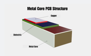
Thermal Clad PCB
1.2 Key Components and Layer Structure of a Thermal Clad PCB
The architecture of a Thermal Clad PCB can be visualized as a three-layer sandwich:
-
Copper Circuit Layer
This is where the signal traces, pads, and vias are etched. Copper thickness can vary depending on current-carrying requirements, often ranging from 1 oz to 3 oz per square foot. For high-current or high-power applications, thicker copper layers may be used. -
Thermally Conductive Dielectric Layer
This is a thin, electrically insulating but thermally conductive material that bonds the copper layer to the metal core. Its thermal conductivity typically ranges from 1.0 W/m·K to over 8.0 W/m·K, depending on the application’s heat dissipation needs. It ensures electrical isolation between the circuit and the metal base while allowing heat to flow freely. -
Metal Core (Aluminum or Copper)
The heart of the Thermal Clad PCB.-
Aluminum cores are lightweight, cost-effective, and provide good thermal conductivity (around 200–235 W/m·K).
-
Copper cores offer even higher thermal conductivity (up to 400 W/m·K) but are heavier and more expensive.
-
Some designs also include solder mask and silkscreen layers for component marking and protection, but these do not significantly affect thermal performance.
1.3 The Evolution from Traditional PCBs to Thermal Clad PCB Solutions
Historically, traditional FR-4 PCBs were sufficient for most consumer electronics because component power density was relatively low. However, modern electronics—particularly LED lighting, power conversion, automotive control units, and industrial drives—pack more power into smaller spaces, generating more heat per square centimeter.
As heat problems worsened, engineers first attempted to manage it with heat sinks, cooling fans, and thermal pads. While these methods help, they also add complexity, cost, and assembly challenges. The concept of integrating the heat-spreading function directly into the PCB structure became increasingly attractive. This gave rise to Thermal Clad PCB technology in the late 20th century, pioneered by companies looking to serve the high-brightness LED market.
Over the years, dielectric materials have improved significantly. Modern Thermal Clad PCBs can achieve low thermal resistance (below 0.3°C/W) and withstand operating temperatures well above 130°C, making them viable for military, aerospace, and high-performance industrial applications.
2. Thermal Clad PCB Materials and Manufacturing Processes
2.1 Copper Foil Types in Thermal Clad PCB (Rolled vs. Electrolytic)
Copper foil is the foundation for signal routing in any PCB, and in a Thermal Clad PCB, the choice of foil type can directly influence both thermal and electrical performance. Two primary copper foil manufacturing methods dominate the industry: rolled copper foil and electrolytic copper foil.
-
Rolled Copper Foil
Produced by mechanically rolling a thick copper ingot into ultra-thin sheets, rolled copper foil has excellent ductility, smooth surface quality, and high mechanical strength. These qualities make it ideal for applications requiring repeated bending or thermal cycling without developing cracks. Rolled foil is more expensive due to the additional mechanical processing involved. -
Electrolytic Copper Foil
Produced by depositing copper from a chemical solution onto a rotating drum in an electrolytic process, this foil is more cost-effective and has fine grain structure that makes it suitable for standard rigid boards. However, its surface is slightly rougher, which can be beneficial for adhesion but less optimal for ultra-high-frequency signals where smoothness matters.
FAQ 1: What is the difference between rolled copper foil and electrolytic copper foil?
Rolled copper foil is produced by mechanically rolling copper into thin sheets, offering better surface quality and mechanical strength, making it suitable for flexing or thermal cycling. Electrolytic copper foil is deposited via an electrolytic process and is more flexible in production, cost-effective, and widely available, but with a slightly rougher surface texture.
2.2 Dielectric Layer Formulations for Thermal Clad PCB Performance
The dielectric layer in a Thermal Clad PCB is a thin but critical component that bonds the copper circuit layer to the metal base while maintaining electrical insulation. Its formulation determines the thermal conductivity, dielectric breakdown voltage, and mechanical adhesion strength.
-
Thermal Conductivity: Measured in watts per meter-kelvin (W/m·K), higher values mean faster heat transfer from the copper to the metal core. High-end dielectrics can exceed 8 W/m·K.
-
Dielectric Strength: Indicates the maximum voltage the layer can withstand before electrical breakdown, typically 2–4 kV.
-
Thickness: Generally ranges from 50 μm to 150 μm. Thinner dielectrics improve heat transfer but may reduce electrical isolation safety margins.
Advanced formulations also include ceramic fillers to enhance thermal conductivity without significantly compromising flexibility or adhesion. Some manufacturers, including SQ PCB, have developed proprietary dielectric blends optimized for high-power LED arrays and EV power modules.
2.3 Metal Core Selection: Aluminum vs. Copper in Thermal Clad PCB Production
The metal core is the heat-spreading backbone of a Thermal Clad PCB. Choosing between aluminum and copper depends on application-specific trade-offs.
-
Aluminum Core
-
Thermal Conductivity: ~200–235 W/m·K
-
Lightweight, cost-effective, corrosion-resistant
-
Ideal for large-scale LED lighting, consumer power supplies, and automotive electronics where weight is a factor
-
-
Copper Core
-
Thermal Conductivity: ~380–400 W/m·K
-
Superior heat spreading and mechanical rigidity
-
Heavier and more expensive
-
Used in military electronics, RF amplifiers, and high-density power modules
-
Some advanced boards even use multi-layer metal core designs, where an aluminum core is bonded to a copper heat spreader for targeted cooling.
2.4 Manufacturing Workflow of Thermal Clad PCB
The production of a Thermal Clad PCB is more complex than standard FR-4 boards due to the integration of the metal core. The general workflow includes:
-
Metal Core Preparation
The aluminum or copper base is cut, deburred, and surface-treated to improve adhesion. -
Dielectric Lamination
The dielectric layer is laminated onto the metal core under heat and pressure, ensuring uniform bonding. -
Copper Lamination
A sheet of copper foil is laminated on top of the dielectric layer, forming the circuit layer foundation. -
Circuit Patterning
Photolithography and etching processes define the copper traces and pads. -
Solder Mask Application
A protective layer is applied to prevent oxidation and solder bridging during assembly. -
Surface Finish
ENIG (Electroless Nickel Immersion Gold), HASL (Hot Air Solder Leveling), or OSP (Organic Solderability Preservatives) are applied depending on the application. -
Final Machining and QC
Boards are routed, drilled, cleaned, and inspected for electrical integrity and thermal performance.
Manufacturing precision is critical — even slight imperfections in dielectric uniformity can cause hot spots, undermining the main purpose of the Thermal Clad PCB.
3. Advantages of Thermal Clad PCB Over Traditional PCB
3.1 Superior Heat Dissipation in Thermal Clad PCB
One of the most compelling advantages of a Thermal Clad PCB over a traditional FR-4 board is its ability to manage and dissipate heat effectively.
In high-power electronics, such as LED lighting systems or motor control units, excessive heat is the primary cause of reduced component lifespan. A standard FR-4 board relies on conduction through its fiberglass-epoxy substrate, which has a thermal conductivity of around 0.3 W/m·K — far too low for demanding applications.
In contrast, a Thermal Clad PCB integrates a metal core (aluminum or copper) with thermal conductivity values ranging from 200 W/m·K to 400 W/m·K, and a thermally conductive dielectric layer that ensures rapid heat transfer from heat-generating components to the metal base. This allows the board to maintain lower operating temperatures, thereby improving component reliability and system performance.
For example, in high-brightness LED modules, using a Thermal Clad PCB can reduce the junction temperature of LEDs by 10–25°C compared to traditional boards — a difference that can double the LED lifespan.
3.2 Enhanced Mechanical Stability in Thermal Clad PCB
Another advantage of a Thermal Clad PCB is its mechanical rigidity and dimensional stability.
-
Traditional PCBs can warp under thermal cycling because FR-4 expands and contracts at a higher coefficient of thermal expansion (CTE) compared to metals. This warping can stress solder joints and lead to micro-cracks.
-
Thermal Clad PCBs, with their metal core, have a much lower and more stable CTE, which means they expand less with heat and resist bending. This stability is essential in automotive electronics and outdoor LED fixtures that undergo repeated heating and cooling cycles.
Additionally, the metal base acts as a structural reinforcement, reducing vibration damage in harsh environments, making these boards popular in military and aerospace applications.
3.3 Thermal Clad PCB in High-Power and LED Applications
Thermal Clad PCB technology is particularly advantageous in applications where components generate significant heat in a small area.
-
LED Lighting: LEDs are extremely sensitive to heat. Every 10°C rise in junction temperature can reduce light output and shorten lifespan. By quickly transferring heat to the metal core, a Thermal Clad PCB ensures consistent brightness and color stability.
-
Power Electronics: In power converters, MOSFETs and IGBTs generate substantial heat during switching. A Thermal Clad PCB can prevent thermal runaway by efficiently channeling heat away from critical components.
-
RF and Microwave Circuits: Thermal stability is crucial for maintaining signal integrity. The low thermal resistance of these boards minimizes frequency drift caused by temperature changes.
3.4 Longevity and Reliability Advantages of Thermal Clad PCB
Heat is one of the biggest enemies of electronics. Lower operating temperatures not only extend component life but also reduce the rate of chemical and mechanical degradation of the PCB materials themselves.
Studies show that reducing a semiconductor’s operating temperature by 10°C can double its mean time between failures (MTBF). By ensuring that critical devices stay cool, a Thermal Clad PCB directly improves system reliability, minimizes maintenance, and reduces downtime.
For mission-critical applications — such as electric vehicle battery management systems, industrial motor drives, and medical diagnostic equipment — the long-term reliability provided by Thermal Clad PCB technology can justify the higher initial cost.
4. Thermal Clad PCB vs. Traditional PCB: Technical Comparisons
4.1 Electrical Performance Differences
While Thermal Clad PCBs are primarily adopted for their thermal advantages, they also bring subtle differences in electrical performance compared to traditional FR-4 boards.
-
Signal Integrity
The dielectric layer in a Thermal Clad PCB can be engineered to have a controlled dielectric constant (Dk) and low dissipation factor (Df), which minimizes signal loss, especially in RF and microwave applications. Traditional FR-4 materials have a Dk of about 4.5, whereas advanced thermal dielectrics can range from 3.0 to 4.0, reducing impedance variations. -
Power Handling
The ability to run thicker copper layers (2 oz, 3 oz, or more) in a Thermal Clad PCB allows for higher current capacity without excessive trace heating. In high-current motor drives, this reduces resistive losses and improves efficiency. -
Temperature-Dependent Resistance Stability
Metal-core boards maintain more consistent copper trace resistance over temperature fluctuations, helping precision analog circuits maintain calibration.
4.2 Thermal Conductivity Ratings and Their Impact
Thermal conductivity is where the performance gap between Thermal Clad PCBs and traditional FR-4 boards becomes undeniable.
| Parameter | FR-4 PCB | Thermal Clad PCB (Aluminum Core) | Thermal Clad PCB (Copper Core) |
|---|---|---|---|
| Dielectric Thermal Conductivity | ~0.3 W/m·K | 1–8 W/m·K | 1–8 W/m·K |
| Metal Core Thermal Conductivity | N/A | ~200–235 W/m·K | ~380–400 W/m·K |
| Thermal Resistance (Typical LED) | 3–5 °C/W | 0.2–0.5 °C/W | 0.1–0.4 °C/W |
The difference is dramatic — a 10× to 20× improvement in heat transfer efficiency means components can run cooler even under the same load, or handle higher power density without overheating.
4.3 Weight, Cost, and Design Trade-offs
While Thermal Clad PCBs have impressive thermal performance, they also bring certain trade-offs:
-
Weight
An aluminum core adds about 1.5–2× the weight of a standard FR-4 board of the same thickness. A copper core can be 3–4× heavier. This can be a factor in aerospace or portable electronics. -
Cost
Manufacturing a Thermal Clad PCB involves extra materials (metal core, thermal dielectric) and processes (lamination, drilling with specialized bits). Expect a cost increase of 20–50% over FR-4 for aluminum core boards, and 50–100% for copper core boards. -
Design Limitations
Thermal Clad PCBs are often single-sided or double-sided in practical applications, as multi-layer designs with metal cores require complex and expensive isolation strategies for vias.
However, in high-power applications, the lifecycle cost savings from reduced failures and longer component life can far outweigh the initial price premium.
4.4 Case Studies Comparing Thermal Clad PCB and Traditional PCB
Case Study 1 – High-Brightness LED Streetlight
-
FR-4 PCB Result: LED junction temperature reached 95°C at full brightness. Noticeable dimming after 6 months.
-
Thermal Clad PCB Result: LED junction temperature held at 72°C. No measurable dimming after 1 year.
Case Study 2 – Industrial Motor Drive
-
FR-4 PCB Result: MOSFET failures within 18 months due to thermal fatigue.
-
Thermal Clad PCB Result: Operating for 3+ years without component failure.
Case Study 3 – RF Amplifier Module
-
FR-4 PCB Result: Frequency drift of 0.5% over operating temperature range.
-
Thermal Clad PCB Result: Frequency drift reduced to 0.15%, maintaining output stability.
These examples demonstrate that, while the Thermal Clad PCB may not be necessary for low-power consumer electronics, it delivers a decisive performance advantage in heat-intensive, reliability-critical environments.
5. Application Scenarios for Thermal Clad PCB
5.1 Automotive Electronics
Modern vehicles have evolved into high-power electronic systems on wheels. Components like engine control units (ECUs), LED headlights, and electric vehicle battery management systems must operate reliably under harsh conditions — including extreme temperature swings, vibration, and moisture.
A Thermal Clad PCB is especially valuable in:
-
LED Headlight Modules – where maintaining brightness and color consistency is critical to driver safety.
-
Motor Controllers and Inverters – where power transistors generate substantial heat.
-
Radar and ADAS Modules – where thermal stability affects radar frequency accuracy and sensor reliability.
The mechanical rigidity of the metal core also helps withstand engine vibration and road shock, preventing solder joint fatigue.
5.2 LED Lighting Systems
High-brightness LEDs are one of the largest markets for Thermal Clad PCB technology. In streetlights, stadium lighting, and architectural illumination, LEDs can lose up to 70% of their brightness over time if junction temperatures are not managed.
With a Thermal Clad PCB, the heat generated by LEDs is transferred rapidly to the metal core, keeping junction temperatures lower and ensuring:
-
Longer lifespan (often 2×–3× compared to FR-4)
-
Better lumen maintenance
-
More consistent color rendering
For manufacturers seeking consistent quality in large-scale LED lighting projects, SQ PCB stands out. They specialize in aluminum-core Thermal Clad PCB fabrication with high thermal conductivity dielectrics, ensuring performance uniformity across thousands of units.
5.3 Power Electronics
Power converters, SMPS units, solar inverters, and industrial motor drives all push high current through their circuits. The heat from switching devices like MOSFETs, IGBTs, and diodes must be removed rapidly to avoid thermal runaway.
A Thermal Clad PCB in power electronics offers:
-
High copper thickness for current handling
-
Direct heat path to chassis or heatsink
-
Improved MTBF for critical components
By integrating the thermal pathway directly into the PCB, designers can often reduce the size and cost of external heatsinks, making the system more compact.
5.4 Renewable Energy Systems
In solar power inverters and wind turbine control systems, boards must operate in outdoor environments with large temperature swings and sustained high power throughput.
A Thermal Clad PCB provides both the thermal dissipation and mechanical strength needed for these long-life, low-maintenance installations. Aluminum-core designs are common here because they balance good thermal performance with lighter weight.
5.5 Industrial and Military Applications
In industrial robotics, radar systems, and aerospace electronics, downtime is costly and sometimes dangerous. Here, Thermal Clad PCB technology ensures that precision and reliability are maintained under heavy loads and extreme temperatures.
Copper-core designs are often used in military applications where maximum thermal conductivity is required, and space constraints prevent large external heatsinks.
6. Thermal Clad PCB Design Considerations and Best Practices
6.1 Thermal Path Optimization in Thermal Clad PCB
When designing a Thermal Clad PCB, the primary goal is to create a low-resistance thermal path from the heat source to the environment. This involves:
-
Component Placement – Position high-heat components directly above the thickest part of the thermal dielectric and metal core area.
-
Thermal Vias – Although the metal core already provides strong conduction, thermal vias can help spread heat more evenly in double-sided designs.
-
Direct Mounting – In some designs, power devices are bolted directly to the PCB’s metal core for maximum heat transfer.
Failure to plan the thermal path can lead to hot spots, negating the benefits of a Thermal Clad PCB.
6.2 Copper Thickness Selection
Copper layer thickness directly impacts both current-carrying capacity and thermal performance.
-
1 oz copper is common for low to medium power designs.
-
2–3 oz copper is typical for high-power LED drivers or industrial motor controls.
-
Over 3 oz copper is used for extreme current loads, but increases cost and manufacturing complexity.
Remember that thicker copper also impacts trace etching resolution, so high-density designs must balance conductivity with routing needs.
6.3 Dielectric Material Choices
The dielectric layer in a Thermal Clad PCB is the critical bridge between the copper circuitry and the metal core.
-
High Thermal Conductivity dielectrics (≥ 2.0 W/m·K) are essential for high-power applications.
-
Thin Dielectric Layers reduce thermal resistance but may increase the risk of breakdown if voltage ratings aren’t properly considered.
-
Electrical Isolation is crucial — the dielectric must withstand the full operating voltage between the copper and the metal core.
6.4 Mechanical Design Constraints
Metal-core PCBs are less flexible than FR-4, meaning that mechanical stress must be accounted for in product design. For example:
-
Avoid forcing the board into a bent enclosure.
-
Use mounting holes and standoffs to evenly distribute stress.
-
Consider CTE (coefficient of thermal expansion) matching for components.
6.5 Partnering with the Right Manufacturer
Because Thermal Clad PCB fabrication involves specialized lamination and drilling processes, it’s important to choose a manufacturer with proven expertise.
For example, SQ PCB offers:
-
High-conductivity aluminum and copper cores
-
Custom dielectric formulations for specific thermal and electrical needs
-
Precision CNC drilling to handle the hardness of metal-core boards without delamination
-
Prototyping and mass production capabilities with consistent quality control
Choosing a partner like SQ PCB can help avoid design-to-production mismatches that cause costly reworks.
7. Manufacturing Process of Thermal Clad PCB
7.1 Raw Material Selection
A Thermal Clad PCB starts with three core layers:
-
Metal Base – Usually aluminum (200–235 W/m·K) or copper (380–400 W/m·K).
-
Dielectric Layer – The thermally conductive yet electrically insulating layer, typically 50–200 μm thick.
-
Copper Foil Layer – 1–3 oz thickness depending on design requirements.
Material selection determines the board’s thermal performance, weight, and mechanical strength from the outset.
7.2 Lamination Process
The lamination process bonds the dielectric layer between the metal base and copper foil. Key factors:
-
Uniform Pressure and Heat – Ensures consistent dielectric thickness and no air gaps.
-
Cleanroom Conditions – Prevents dust contamination, which could create thermal voids.
-
Adhesion Promoters – Surface treatments improve bonding between copper and dielectric.
7.3 Drilling and Routing
Unlike FR-4, drilling through a Thermal Clad PCB requires specialized carbide or diamond-coated drill bits because of the hardness of the metal base.
-
CNC Drilling – High precision to avoid burrs and maintain hole wall integrity.
-
Routing and Punching – For board outline shaping; mechanical routing is preferred for thicker cores.
7.4 Circuit Patterning
The copper layer is patterned using photolithography and etching:
-
Photoresist Application – Coating copper with light-sensitive resist.
-
UV Exposure and Developing – Defines the circuit image.
-
Etching – Removes unwanted copper, leaving the desired traces.
7.5 Solder Mask and Surface Finish
Solder mask application is critical for solder joint reliability. Since metal-core boards may experience higher thermal cycling, finishes like ENIG (Electroless Nickel Immersion Gold) or OSP (Organic Solderability Preservative) are preferred for their durability.
7.6 Assembly Considerations
Metal-core boards retain heat longer during reflow soldering, so thermal profiling must be adjusted to prevent:
-
Cold solder joints on large copper pads.
-
Thermal stress to sensitive components.
Pick-and-place machines and reflow ovens must be set with precise temperature ramps.
7.7 Testing and Quality Control
Thermal Clad PCB testing includes:
-
Electrical Testing – Continuity and insulation resistance.
-
Thermal Imaging – Identifies uneven heat dissipation.
-
Mechanical Inspection – Checks for warpage or delamination.
High-reliability sectors (automotive, aerospace) may also require thermal shock testing and long-term thermal aging tests.
8. Cost-Benefit Analysis of Thermal Clad PCB vs. Traditional PCB
8.1 Initial Material and Manufacturing Costs
At first glance, a Thermal Clad PCB is more expensive than a traditional FR-4 PCB because:
-
The metal core (aluminum or copper) is more costly than glass-reinforced epoxy.
-
Specialized lamination and drilling processes add manufacturing complexity.
-
Lower economies of scale compared to traditional PCBs in certain markets.
However, this higher upfront cost often pays for itself over the product’s lifespan.
8.2 Operational Efficiency Gains
Thermal Clad PCBs allow for tighter component packing and reduced heatsink size, which:
-
Lowers the overall footprint of the final product.
-
Reduces weight in portable or automotive systems.
-
Minimizes energy losses caused by overheating components.
For example, an LED streetlight using Thermal Clad PCB technology can operate at lower junction temperatures, improving luminous efficacy by up to 20%.
8.3 Maintenance and Downtime Reduction
In applications like industrial motor controllers or telecom power supplies, downtime is costly.
-
Fewer failures due to overheating means fewer repair calls.
-
Extended component life reduces warranty claims.
-
Improved thermal stability enhances long-term reliability, particularly in mission-critical applications.
8.4 Lifecycle Cost Perspective
When considering Total Cost of Ownership (TCO):
-
Higher upfront investment is offset by lower replacement rates.
-
Energy savings from efficient thermal management further reduce operating expenses.
-
Enhanced reliability can improve a brand’s reputation, indirectly boosting sales.
8.5 Example ROI Calculation
Let’s take a high-power LED floodlight project as an example:
-
FR-4 PCB version: $10/unit cost, 3-year average lifespan before lumen depreciation makes replacement necessary.
-
Thermal Clad PCB version: $18/unit cost, 8-year average lifespan.
Even ignoring maintenance labor, the cost per year of service is:
-
FR-4: $10 ÷ 3 ≈ $3.33/year
-
Thermal Clad PCB: $18 ÷ 8 = $2.25/year
That’s ~33% lower annual cost despite the higher purchase price.
9. Reliability and Longevity Factors in Thermal Clad PCB Applications
9.1 Thermal Cycling and Fatigue Resistance
A major reliability challenge for electronics is thermal cycling — the repeated heating and cooling during operation.
-
Traditional FR-4 PCBs can suffer from microcracking in copper traces or delamination of layers due to mismatched thermal expansion.
-
A Thermal Clad PCB uses a metal core with better heat conduction and more uniform temperature distribution, reducing localized thermal stress.
This uniformity helps prevent solder joint fatigue and extends component life.
9.2 Dielectric Integrity Over Time
The dielectric layer in a Thermal Clad PCB must endure:
-
Continuous heat exposure (often 80–120°C in normal operation)
-
Occasional high-temperature spikes (up to 200°C in transient events)
-
High voltage isolation requirements in power electronics
High-quality dielectrics maintain both thermal conductivity and electrical insulation for many years without breakdown.
9.3 Corrosion Resistance
Because the metal core (especially aluminum) is more prone to corrosion than FR-4’s glass-fiber base, manufacturers:
-
Apply anodization or conversion coatings to aluminum cores.
-
Use protective solder masks and edge sealing to prevent moisture ingress.
This protection is critical in outdoor LED lighting, marine electronics, and industrial environments.
9.4 Mechanical Robustness
The rigidity of a Thermal Clad PCB adds mechanical stability, which helps in:
-
Vibration-heavy environments (automotive, aerospace)
-
Portable equipment that experiences frequent handling
However, this rigidity also means less flexibility — bending the board can cause cracks, so designs must accommodate this.
9.5 Long-Term Thermal Stability
The biggest longevity advantage of a Thermal Clad PCB is consistent operating temperature. Components operating at lower average temperatures can last 2×–5× longer, according to Arrhenius reliability models.
10. Common Design Mistakes with Thermal Clad PCB and How to Avoid Them
10.1 Ignoring Thermal Path Continuity
Many designers assume the metal core automatically solves all heat problems. In reality:
-
Placing high-power components away from direct thermal paths to the metal base drastically reduces efficiency.
-
The dielectric layer should be as thin as possible while meeting voltage isolation requirements.
-
Copper planes should be thermally connected to heat sources via wide traces or filled polygons.
10.2 Over-Specifying Copper Thickness
While thicker copper can carry more current, it also:
-
Increases manufacturing costs significantly.
-
Reduces routing density due to wider isolation gaps.
-
Makes etching more challenging, risking trace definition issues.
For most LED drivers and power circuits, 2 oz copper is a good balance between thermal and routing needs.
10.3 Neglecting Mechanical Mounting Considerations
A Thermal Clad PCB is rigid and heavier than FR-4.
-
Without proper standoffs, vibration can lead to cracked solder joints.
-
Incorrect mounting torque on screws can warp the dielectric layer.
-
Avoid “floating” the PCB with only connector support — always secure it physically.
10.4 Choosing the Wrong Core Material
Some projects overpay for copper cores when aluminum cores would suffice.
-
Copper cores are justified only when extreme thermal conductivity is required.
-
For most applications (LED, industrial controls), aluminum offers the best cost-performance ratio.
10.5 Underestimating Heat During Reflow Soldering
Metal-core boards retain heat longer than FR-4.
-
If reflow profiles aren’t adjusted, you can overheat sensitive components.
-
Controlled cooling is just as important as heating to avoid thermal shock.
10.6 Not Leveraging Manufacturer Expertise
Manufacturers like SQ PCB can provide design for manufacturability (DFM) feedback, helping avoid costly redesigns.
-
Early consultation can prevent dielectric thickness mismatches.
-
They can suggest optimal copper weights and plating options for your budget and performance needs.
Conclusion
Thermal Clad PCB technology is evolving beyond its original LED and power supply niche. As materials science, manufacturing techniques, and thermal modeling improve, we will see smaller, more powerful, and more reliable electronic devices — without the bulky heatsinks of the past.
The decision between a Thermal Clad PCB and a traditional PCB will increasingly be about strategic product positioning: performance, longevity, and sustainability versus lowest possible initial cost.
And in that equation, as we’ve seen, Thermal Clad PCBs are becoming the smarter long-term choice.
FAQ 1: What is the difference between rolled copper foil and electrolytic copper foil?
Rolled copper foil is produced by mechanically rolling copper into thin sheets, which offers better surface quality, higher tensile strength, and flexibility — making it ideal for flexible circuits or applications requiring repeated bending.
Electrolytic copper foil is created via electro-deposition, which results in a slightly rougher surface but is more cost-effective and widely available. It’s suitable for most rigid PCB applications, including many Thermal Clad PCB designs.
FAQ 2: Why choose aluminum vs. copper core for a Thermal Clad PCB?
-
Aluminum Core: Lighter, more cost-effective, and sufficient for most LED and mid-power applications.
-
Copper Core: Offers nearly twice the thermal conductivity, better for extremely high-power density circuits, but is heavier and more expensive.
The choice depends on performance targets, weight constraints, and budget.
FAQ 3: Can Thermal Clad PCBs completely eliminate the need for heatsinks?
Not always. While a Thermal Clad PCB can significantly reduce the size and cost of heatsinks, in very high-power designs, additional heatsinking or active cooling may still be necessary. The main benefit is that you can often use smaller, lighter, and cheaper thermal solutions without sacrificing performance.
FAQ 4: How does a Thermal Clad PCB improve solder joint life?
By spreading heat evenly and preventing localized overheating, a Thermal Clad PCB reduces the expansion/contraction stress on solder joints during temperature changes. This minimizes microfractures and extends the mechanical and electrical reliability of the connection.
FAQ 5: Can I use a Thermal Clad PCB in multi-layer designs?
Yes, but the design is more complex. Most Thermal Clad PCBs are single-sided because drilling through the metal core for vias is challenging. Multi-layer designs typically involve insulating sub-layers above the metal core or hybrid PCB structures where only certain layers have a thermal clad base.

- long board pcb
- Flexible PCBs
- Special PCB
- Express Printed Circuit Board
- Pcb Prototype
- LED PCB
- PCB
- Printed Circuit Board
- Pcb meaning
- Pcb manufacturer
- Rigid pcb board
- Rigid Flex PCB
 Quote
Quote
 E-mail