1: Introduction to HDI PCB and the Role of SBU Technology
1.1 Introduction to the Evolution of HDI PCB Designs
In the realm of electronic design, miniaturization and performance enhancement have become inseparable goals. The advent of High-Density Interconnect (HDI) printed circuit boards marked a significant departure from conventional multilayer designs. These modern interconnect platforms are engineered to offer more functionality in smaller footprints while supporting increasingly complex circuitry and high-speed signal transmission.
Initially, the transition from single-sided and double-sided PCBs to multilayer designs was sufficient to accommodate growing electrical demands. However, as consumer electronics, medical devices, and military-grade systems demanded more power in tighter spaces, HDI architecture emerged as a technological necessity. It is in this context that Sequential Build-Up (SBU) technology became indispensable to HDI PCB fabrication.
The goal of this article is to provide a deep understanding of SBU technology as it applies to HDI PCB development. Through technical breakdowns, manufacturing insights, and strategic evaluations, the discussion aims to offer engineers and designers a comprehensive reference for integrating SBU techniques into next-generation circuit boards.
1.2 What is SBU Technology in the Context of HDI PCB?
Sequential Build-Up (SBU) technology refers to the process of constructing multiple dielectric and conductive layers in a PCB through a series of additive lamination cycles. Unlike traditional PCBs, which are often built symmetrically and simultaneously, HDI PCB structures involving SBU are fabricated by adding one or more layers at a time in a stepwise manner.
SBU enables the formation of microvias—extremely small holes that connect adjacent layers—along with precise laser drilling and controlled impedance routing. This layered growth process allows for flexible routing paths and higher component density without compromising signal integrity or thermal performance.
The concept of SBU aligns with the principle of “design freedom” in HDI systems. Instead of being limited by pre-defined stackups, engineers can selectively add interconnection layers only where needed. The result is a PCB that is not only denser but also more efficient in layer usage and cost management when optimized effectively.
Personal Insight:
From a designer’s perspective, SBU offers a practical pathway to innovation. It eliminates unnecessary complexity in areas where interlayer connections aren’t needed while enabling concentrated circuit functionality in high-performance zones. This aspect is especially valuable when developing compact IoT devices or advanced sensor modules.
1.3 The Historical Development of HDI PCB and the Rise of SBU
The first implementations of high-density PCBs can be traced back to the late 1980s and early 1990s, driven by telecommunications and aerospace industries. As components grew smaller due to advances in silicon design, the need for a matching interconnection strategy became more urgent. Early attempts to reduce board size and increase I/O (input/output) connections revealed the limitations of traditional via drilling and copper plating methods.
SBU technology began gaining traction when laser drilling systems became commercially viable. By integrating SBU techniques, engineers could stack multiple signal layers while preserving electrical characteristics. The development of resin-coated copper foils, photoimageable dielectrics, and improved registration methods accelerated the industrial adoption of this process.
In the current landscape, the majority of cutting-edge HDI boards—especially those found in smartphones, tablets, automotive ECUs, and AI hardware—rely on at least one layer of SBU to achieve their form factor and performance metrics.
1.4 Why HDI PCB Requires a Different Fabrication Approach
Unlike traditional PCBs, which are largely two-dimensional in their design thinking, HDI boards with SBU structures adopt a three-dimensional connectivity model. This difference introduces a number of design and fabrication challenges:
-
Microvia Control: Laser-drilled vias must be perfectly formed and metallized.
-
Dielectric Material Selection: Special polymers must support fine-line imaging and high-frequency operation.
-
Registration Accuracy: Layer alignment must be within microns to ensure interlayer continuity.
-
Thermal Management: Increased circuit density demands better thermal spreading solutions.
-
Design-for-Manufacturing (DFM): SBU layers complicate manufacturing, making early DFM engagement critical.
Therefore, SBU is not merely a construction method—it is a strategic response to the specific needs of HDI circuit board applications. It empowers designers to go beyond conventional limitations, but only when integrated with rigorous process control and quality assurance protocols.
Personal Thought:
It’s not just about making things smaller—it’s about enabling new possibilities. From biometric sensors in wearables to radar systems in EVs, the ability to embed SBU within HDI PCBs is fundamentally reshaping what electronic devices can do.
1.5 Key Materials Used in SBU-Based HDI PCB Manufacturing
The successful deployment of SBU techniques in HDI PCB designs relies heavily on the selection and performance of advanced materials. Each material serves a distinct role in ensuring mechanical integrity, electrical performance, and process compatibility:
-
Dielectric Films: These are typically made from epoxy, polyimide, or fluorinated materials that can withstand repeated lamination and support high-resolution imaging.
-
Resin-Coated Copper Foils (RCC): Used as a base for photoimaging, RCC combines the flexibility of resin with the conductivity of copper, facilitating tight line/space designs.
-
Laser-Drillable Materials: These materials allow clean microvia formation without excessive debris or glass fiber protrusion.
-
Prepregs and Cores: These must exhibit low z-axis expansion and high peel strength for optimal reliability during thermal cycling.
Modern HDI stacks often include a mix of low-loss and standard materials to balance performance and cost. For instance, high-speed signal layers may be fabricated using low-Dk materials while power-ground layers use conventional FR-4 variants.
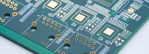
HDI PCB
2: SBU Layer Formation Techniques in HDI PCB Fabrication
2.1 Overview of SBU Formation in HDI PCB Structures
The Sequential Build-Up (SBU) process is the backbone of HDI PCB manufacturing. It enables designers to build high-density interconnect boards by layering dielectric materials and copper circuitry in a controlled, iterative sequence. This step-by-step lamination process allows for complex signal routing and vertical interconnection using microvias—tiny, laser-drilled vias that connect adjacent layers.
Each SBU cycle typically adds one or two copper/dielectric layers to the board and may involve several critical sub-processes: dielectric lamination, via formation, metallization, and patterning. These cycles can be repeated multiple times depending on the final stack-up and performance needs.
What makes SBU particularly powerful is that each added layer is independent from the original core, allowing much more flexibility in interconnect density and layout strategy. This approach is particularly well-suited for devices that demand fine-pitch BGA components, differential pairs, or tightly constrained routing layers.
2.2 Common Stack-Up Configurations in HDI PCB with SBU
The choice of stack-up configuration has a major impact on the reliability, performance, and cost of an HDI PCB using SBU technology. Some of the most prevalent configurations include:
-
1+N+1 Structure: This is the most basic SBU configuration, where one buildup layer is added to each side of a traditional core. It’s ideal for simpler HDI designs such as smartphones or GPS modules.
-
2+N+2 Structure: Two SBU layers are added to each side of the core. This configuration supports more complex routing and higher I/O counts, often used in tablets, notebooks, or advanced networking gear.
-
3+N+3 and Beyond: Advanced systems with even more layers are common in aerospace, server boards, and high-end AI accelerators. These involve three or more sequential layers on each side, requiring tighter process control and higher investment in materials and inspection tools.
The “N” in these structures represents the number of traditional layers in the central core. This core is typically a fully fabricated double-sided or multilayer board with through-holes that serve as the foundational electrical and mechanical base.
2.3 Microvia Types Used in SBU HDI PCB
Microvias are the hallmark of the SBU process. They offer localized vertical interconnection between layers without consuming the space and mechanical stress of traditional through-holes. Depending on the design, several types of microvias can be used:
-
Blind Vias: These connect outer layers to one or more inner layers without going all the way through the board.
-
Buried Vias: Located completely within internal layers, these vias are invisible from the outer surfaces.
-
Stacked Microvias: Formed by drilling vias directly above one another across multiple buildup layers, enabling more complex 3D routing.
-
Staggered Microvias: Offset vertically in a stair-step pattern, they provide better mechanical integrity and avoid plating challenges often associated with stacked structures.
2.4 Dielectric Deposition in SBU Cycles for HDI PCB
Each SBU cycle begins with the deposition of a dielectric material over an existing substrate. There are several approaches to achieving this:
-
Lamination of Resin-Coated Copper (RCC): RCC is laminated under heat and pressure, fusing it to the underlying layer while providing a new copper surface for imaging.
-
Application of Photo-Imageable Dielectrics (PID): These are spun or sprayed onto the surface and then exposed to UV light through a mask to define microvia positions.
-
Vacuum Lamination of Film Dielectrics: Used to ensure bubble-free adhesion, particularly important for ultra-fine designs and high-reliability environments.
The chosen dielectric must have properties such as low loss, high thermal stability, and compatibility with laser drilling.
2.5 Laser Drilling in HDI PCB SBU Fabrication
Once the dielectric is in place, laser drilling is performed to create microvias. CO₂ or UV lasers are used depending on the dielectric’s composition. Critical parameters include:
-
Spot Size: Typically 20–100 μm, depending on resolution needs.
-
Drill Depth: Must precisely stop at the copper layer beneath without over-etching.
-
Aspect Ratio: Microvias usually maintain a ratio of less than 1:1 to ensure reliable plating.
Quality control at this stage is vital. Improperly formed microvias can lead to open circuits, weak metallization, or thermal fatigue issues over time.
2.6 Copper Deposition and Patterning in HDI PCB SBU
After drilling, the microvias must be metallized to become functional interconnects. This process includes:
-
Desmearing and Plasma Cleaning: To remove drilling residues and prepare the surface.
-
Electroless Copper Deposition: A thin seed layer is deposited inside vias and across the surface.
-
Electroplating: Adds bulk copper to the microvia barrels and copper traces on the surface.
-
Patterning via Photolithography: UV light is used to define the circuit pattern, followed by etching to remove unwanted copper.
Each SBU layer is thus built up with precision—connecting seamlessly to the previous one while maintaining electrical and thermal continuity.
2.7 Alignment and Registration for Layer-to-Layer Accuracy
As more SBU cycles are performed, maintaining precise registration between layers becomes increasingly difficult. Advanced HDI PCB manufacturing facilities use:
-
X-ray and Optical Registration Systems: For real-time alignment feedback.
-
Fiducial Markers and Etch Targets: Embedded in the board to verify placement during and after each cycle.
-
Laser Direct Imaging (LDI): Helps achieve better accuracy than traditional mask aligners, particularly in tight-pitch layouts.
Even minor misalignments in stacked microvias can result in functional failures. This underscores the critical nature of registration in the SBU process.
3: Material Selection Criteria for HDI PCB with SBU Technology
3.1 Introduction to Material Requirements in HDI PCB Manufacturing
The success of any HDI PCB that utilizes Sequential Build-Up (SBU) technology is highly dependent on the properties of the materials used throughout the fabrication process. Materials must not only meet the electrical and mechanical demands of the end application but also be compatible with complex processing stages like laser drilling, lamination, and fine-line etching.
Because the SBU method builds each dielectric and conductive layer in a step-by-step process, every new layer must exhibit a high degree of thermal and dimensional stability. Furthermore, in high-frequency or high-speed applications, the material’s dielectric properties and surface roughness significantly influence signal integrity and loss characteristics.
3.2 Key Material Categories for HDI PCB SBU Construction
Materials involved in HDI PCB SBU processes can be grouped into several essential categories:
-
Core Laminates: These form the foundation of the PCB and provide structural support.
-
Prepreg and Bonding Sheets: Used for interlayer bonding, especially in the central stack-up.
-
Dielectric Layers for SBU Cycles: Insulative layers that separate copper conductors and accommodate microvias.
-
Conductive Copper Foils: Serve as the basis for the circuitry and microvia interconnection.
-
Laser-Drillable Films: Optimized for smooth via formation and minimal debris generation.
Each of these material types must be carefully matched to the desired application, whether it involves power delivery, high-speed data transmission, or RF functionality.
3.3 Dielectric Constant and Loss Tangent Considerations
One of the most critical criteria for dielectric materials in HDI PCB SBU applications is their dielectric constant (Dk) and dissipation factor (Df). These parameters influence the board’s impedance and signal loss characteristics:
-
Lower Dk (2.5–3.8) is preferred for high-speed signals to reduce propagation delay and crosstalk.
-
Low Df (<0.005) minimizes dielectric loss, ensuring clearer, faster signal transmission over long traces.
High-frequency boards, such as those used in 5G modules or radar systems, require specialty materials like PTFE, hydrocarbon-ceramic blends, or low-loss epoxy formulations.
By contrast, consumer electronics with moderate speed requirements may use advanced FR-4 variants that offer a balance between performance and cost.
3.4 Thermal Stability and Z-axis Expansion in HDI PCB Materials
Sequential lamination involves repeated thermal cycles, and as such, materials used in SBU processes must exhibit:
-
High Glass Transition Temperature (Tg): A Tg above 170°C is recommended to prevent softening or deformation during lamination.
-
Low Coefficient of Thermal Expansion (CTE): Especially in the Z-axis, to ensure reliability during via drilling and copper plating.
-
Excellent Peel Strength: To maintain adhesion between copper and dielectric layers throughout mechanical stress cycles.
Boards subject to thermal shock, such as those in automotive or aerospace applications, benefit from reinforced materials like polyimide or glass-filled epoxies that resist warpage and cracking.
3.5 Laser Drill Compatibility and Material Smoothness
SBU-based HDI PCBs rely heavily on laser drilling to create microvias. For this reason, dielectric layers and copper foils must support:
-
Clean Ablation Characteristics: The material should vaporize cleanly without leaving excessive char or delamination.
-
Thin and Uniform Layers: To support microvias with controlled aspect ratios.
-
Surface Smoothness: Reduces signal reflection and improves conductor etch fidelity.
Special photoimageable dielectrics (PIDs) or resin-coated copper (RCC) sheets are often used due to their fine-resolution capabilities and compatibility with UV or CO₂ laser wavelengths.
3.6 Resin Flow and Fill Performance in Lamination
In SBU cycles, the flow and curing behavior of resin materials significantly affects void formation, copper coverage, and dielectric consistency. Materials must:
-
Provide Complete Fill Around Microvias: To prevent air gaps and delamination during operation.
-
Exhibit Predictable Flow Under Heat and Pressure: Critical for uniform lamination and reducing misregistration.
-
Maintain Stability in High-Humidity or Harsh Environments: For military or industrial applications, moisture resistance becomes a key criterion.
Proper resin selection also influences how well the copper layer adheres, directly impacting plating uniformity and overall mechanical integrity.
3.7 Environmental Compliance and Halogen-Free Options
As environmental regulations tighten globally, many HDI PCB manufacturers have shifted toward halogen-free or RoHS-compliant materials. These materials must deliver high performance while minimizing environmental impact.
Although halogen-free materials tend to have higher CTE and reduced thermal conductivity, advancements in filler technology have begun to close the performance gap. Their use is particularly important in European and Japanese markets, where green electronics regulations are strictly enforced.
4: HDI PCB Design Considerations with SBU Layers
4.1 Introduction to HDI PCB Design Complexity in SBU Systems
The design phase of any HDI PCB project is where functionality, manufacturability, and cost converge. Incorporating Sequential Build-Up (SBU) technology adds an additional layer of complexity to design, requiring strategic thinking in terms of layer count, microvia configuration, signal routing, thermal behavior, and mechanical performance.
SBU layers offer unparalleled routing freedom and electrical performance benefits—but they also introduce constraints in terms of space, cost, registration accuracy, and fabrication tolerances. Therefore, successful HDI PCB design with SBU relies on a holistic understanding of both electrical engineering and manufacturing process intricacies.
4.2 Routing Density and Pad Pitch Considerations
One of the main motivations for adopting HDI PCB architecture with SBU layers is to accommodate components with fine-pitch ball grid arrays (BGAs), land grid arrays (LGAs), or chip-scale packages (CSPs). As I/O counts increase and pin pitches shrink below 0.5 mm, traditional via fan-out strategies become unfeasible.
SBU technology solves this by allowing microvias to be placed directly beneath BGA pads (via-in-pad), or to stagger blind microvias in layers just below the pads. When designing for such high-density areas, it is critical to:
-
Use non-functional pad removal to reduce parasitic capacitance.
-
Avoid trace routing directly beneath sensitive RF paths unless shielded.
-
Observe minimum trace width/spacing rules (typically 50–75 μm) based on fabricator capabilities.
Design software with HDI-aware rulesets can automate many of these constraints, preventing costly errors during layout.
4.3 Stack-Up Symmetry and SBU Layer Planning
Proper layer planning in HDI PCB design requires thoughtful stack-up development. While SBU layers enable selective addition of routing or power/ground planes, layer symmetry should still be maintained to prevent warping or bowing during lamination.
Key design strategies include:
-
Balanced SBU layering: If 2 buildup layers are added to one side of the core, a similar number should be added to the other side.
-
Power-ground pairings: Optimize signal return paths and minimize EMI by designing power-ground layer pairs adjacent to high-speed signal layers.
-
Interconnect path analysis: Reduce the number of vias per net where possible, as each transition introduces impedance discontinuity and increases signal loss.
Simulation tools like SI/PI (Signal Integrity/Power Integrity) modeling can help identify which layer configurations will yield the best signal performance under real-world operating conditions.
4.4 Microvia Type and Placement Strategy
The decision to use stacked versus staggered microvias is not only a fabrication issue but also a design one. Stacked vias enable vertical routing efficiency but increase risk of failure under thermal or mechanical stress. Staggered vias improve reliability but require more horizontal routing space.
Designers should evaluate:
-
Thermal profile of the application: Environments with rapid temperature cycling (e.g., automotive) benefit from staggered microvias.
-
Mechanical loading conditions: Boards subject to flexing or vibration require mechanically robust via structures.
-
Available layer count: High-layer-count HDI designs (3+N+3 or more) often favor stacked vias in critical vertical interconnects to save space.
It’s also essential to apply via aspect ratio control—microvias typically maintain a depth-to-diameter ratio of less than 1:1 to ensure reliable copper plating and minimize cracking.
4.5 Signal Integrity Management in HDI PCB SBU Designs
With the reduction in trace length and layer spacing in HDI designs, maintaining signal integrity becomes more challenging. Designers must address:
-
Controlled impedance routing: Use differential pair and impedance calculators to set trace width/spacing based on dielectric constants and copper thickness.
-
Reflections and crosstalk: Minimize layer transitions and ensure proper via stubbing or backdrilling where necessary.
-
Stub reduction in vias: Use laser-drilled blind vias instead of through-holes wherever possible to reduce reflections and maintain bandwidth.
In many cases, high-speed digital designs (e.g., DDR4, PCIe, USB 3.x) will benefit from embedded capacitance layers or low-Dk dielectrics placed near signal layers to improve performance.
4.6 Thermal Management Strategies in SBU-Enabled HDI PCB
The compact size of HDI boards and dense integration of ICs lead to significant thermal design challenges. SBU layers offer an opportunity to implement targeted thermal pathways, such as:
-
Thermal via arrays: Microvias beneath heat-generating ICs can provide vertical thermal conduction to internal copper planes.
-
Copper planes in buildup layers: Add thermal spreading layers within the SBU stack-up to dissipate localized heat.
-
Thermal interface materials (TIMs): Optimize heat transfer between the PCB and heatsinks or metal chassis using conformable TIMs placed over heat-critical components.
Thermal modeling software like FloTHERM or ANSYS Icepak can simulate heat flow within HDI PCB structures, guiding decisions on layer usage and via placement.
4.7 Design for Manufacturability (DFM) and Yield Optimization
Designing for manufacturability is especially important in HDI PCB SBU-based structures due to the fine geometry and tight tolerances involved. Common DFM principles include:
-
Avoiding over-reliance on stacked microvias unless necessary, due to increased failure risk and cost.
-
Spacing vias adequately from traces and pads to avoid etching defects or solder bridging.
-
Matching material coefficients of expansion (CTEs) to reduce stress across SBU layers.
Early collaboration with the PCB fabricator is strongly advised. Many manufacturers provide design rule check (DRC) files or HDI stack-up templates to accelerate layout and ensure compatibility with their capabilities.
5: Sequential Build-Up (SBU) Layering Process in HDI PCB Manufacturing
5.1 Understanding the Sequential Nature of SBU in HDI PCB
At the heart of modern HDI PCB manufacturing lies the Sequential Build-Up (SBU) process—a layer-by-layer method that strategically constructs interconnect structures and dielectric layers with extreme precision. Unlike traditional multilayer PCBs, where all layers are pressed and laminated in one operation, SBU allows for each buildup layer to be fabricated, drilled, plated, and patterned separately.
This modular layering method is essential for producing fine-pitch, high-density boards, particularly when microvias are required to connect individual layers without the space-consuming nature of full-thickness through-holes.
The stepwise character of SBU means each new layer becomes the foundation for the next, demanding consistent registration, flatness, and cleanliness. Any error in earlier stages will compound in subsequent ones, which makes process control critical.
5.2 Step 1: Formation of the Core Substrate
Every SBU-based HDI PCB begins with a well-prepared core laminate—usually a 2-layer or multilayer conventional PCB that forms the structural base. This core includes fully drilled and plated through-holes, power/ground planes, and critical signal traces.
Key preparation steps include:
-
Surface planarization to ensure flatness.
-
OSP (Organic Solderability Preservative) or ENIG finish if the buildup begins immediately.
-
Surface cleaning to remove contaminants prior to lamination.
The quality of this foundational core directly affects the registration and alignment of all subsequent SBU layers.
5.3 Step 2: Dielectric Lamination for the First Buildup Layer
Once the core is completed, the first SBU cycle begins with the lamination of dielectric material:
-
RCC (Resin-Coated Copper) or PPI (Photoimageable Polyimide) is laminated onto the core using vacuum heat pressing.
-
The resin flows and fills surface topography, then cures to form a stable insulating layer.
-
If no copper is included, a copper foil is added afterward for seed layer formation.
The choice between RCC and PPI depends on the desired resolution, via structure, and processing capability. For ultra-fine-line circuits, photoimageable dielectrics offer better dimensional control.
5.4 Step 3: Laser Drilling of Microvias
With the dielectric in place, laser drilling creates blind microvias that connect the newly added layer to the layer below. This is one of the most critical steps in the SBU process.
Key parameters include:
-
Wavelength: UV lasers offer precision with minimal thermal damage; CO₂ lasers are cost-effective but require more control.
-
Depth Control: Must stop cleanly on the copper pad below, avoiding overdrill or underdrill.
-
Debris Removal: Plasma cleaning or desmear is performed to prepare the via wall for metallization.
Precision in laser drilling ensures electrical continuity and plating integrity in the final product.
5.5 Step 4: Via Metallization and Surface Copper Plating
Once microvias are formed, they must be electrically conductive. This involves a series of metallization steps:
-
Desmear and activation of the via wall using plasma and chemical treatment.
-
Electroless copper deposition (seed layer) provides the base for electroplating.
-
Electroplating thickens copper inside the vias and over the dielectric surface.
The copper layer also prepares the surface for future circuit patterning. Plating uniformity is critical here—especially in stacked via designs, where weak plating in lower layers can cause field failures.
5.6 Step 5: Circuit Pattern Imaging and Etching
With copper on the surface, the next step is to define the circuit traces:
-
A photoresist is applied and imaged using LDI (Laser Direct Imaging) or a phototool.
-
The exposed copper is etched away, leaving only the desired traces and pads.
-
Residual resist is stripped in a chemical bath.
This photolithography process must be tightly controlled to maintain trace width and spacing within tolerances, often as tight as ±10 μm.
5.7 Step 6: Repeating SBU Cycles for Multilayer Buildup
To add more routing or signal layers, additional SBU cycles are performed:
-
Laminate new dielectric over the patterned surface.
-
Laser drill new microvias (stacked or staggered).
-
Metallize and plate vias and surface copper.
-
Image and etch new circuit layers.
This iterative process continues until the full HDI stack-up is realized. The number of SBU layers varies by design—some smartphones require only one or two, while networking devices or military systems may demand five or more.
Each additional layer increases manufacturing complexity, cost, and risk of misalignment or via failure. Thus, careful stack-up planning and rigorous process controls are required throughout.
5.8 Step 7: Final Lamination, Solder Mask, and Surface Finish
After all SBU layers are in place, the HDI PCB enters its final stages:
-
Final lamination bonds the full stack under pressure.
-
Solder mask application protects the circuitry and defines pad openings.
-
Surface finish (e.g., ENIG, OSP, immersion silver) is applied to exposed copper pads for solderability and protection.
Final inspection, AOI (Automated Optical Inspection), and electrical testing are conducted to ensure all layers function as intended.
6: Comparison Between SBU and Traditional Multilayer PCB Techniques
6.1 Introduction to the Need for Comparison
As electronic devices become more compact and powerful, engineers are increasingly faced with a pivotal question during early-stage product development: Should the project use conventional multilayer PCB methods or adopt SBU-based HDI PCB strategies?
While both approaches aim to create multi-layer interconnect platforms, the methods differ significantly in structure, manufacturing complexity, performance capabilities, and cost implications. A nuanced comparison helps guide design choices based on application-specific requirements, cost constraints, and fabrication capabilities.
6.2 Structural Differences: SBU vs Traditional Multilayer PCB
At the core of the difference lies how the layers are constructed.
-
Traditional Multilayer PCBs are manufactured using a single lamination process. All internal layers are pre-fabricated and stacked together, followed by drilling of through-holes that connect all layers simultaneously.
-
SBU-Based HDI PCBs, on the other hand, build up outer layers sequentially. Each SBU cycle involves the addition of dielectric and copper layers, laser-drilled microvias, and independent imaging and plating steps.
| Feature | Traditional Multilayer PCB | SBU-Based HDI PCB |
|---|---|---|
| Layer Formation | All layers laminated in one step | Layers built one by one (SBU cycles) |
| Via Type | Through-hole vias | Microvias (blind, buried, stacked) |
| Interconnect Depth Control | Limited | Precise, layer-to-layer |
| Routing Density | Moderate | Very High |
6.3 Via Technology Comparison
Vias are the key to signal routing in any PCB. Traditional PCBs utilize mechanically drilled through-holes, which connect all layers but occupy more space and cannot be placed under components like BGAs.
SBU-enabled HDI PCBs use laser-drilled microvias, which:
-
Enable via-in-pad and staggered/stacked configurations
-
Reduce parasitic inductance and capacitance
-
Allow tighter component placement and higher I/O counts
| Metric | Through-Hole Via | Microvia (SBU) |
|---|---|---|
| Minimum Diameter | ~0.2–0.3 mm | ~0.05–0.1 mm |
| Aspect Ratio | Up to 10:1 | <1:1 |
| Placement | Board corners, fan-outs | Under components, dense zones |
| Electrical Performance | Lower | Higher (shorter path, less noise) |
6.4 Fabrication Complexity and Yield Management
SBU processes introduce new challenges in fabrication precision and process control. Every SBU layer must align perfectly with the previous one, and microvia quality must be verified at each step.
-
Traditional multilayer PCBs are easier to fabricate at scale and offer high yields due to their consolidated process.
-
SBU-based PCBs require tighter process control (laser drilling, plasma desmear, precision plating) and advanced equipment.
Though yields may be lower in early SBU adoption stages, experienced HDI fabricators achieve excellent reliability through rigorous inline testing and optical verification methods.
6.5 Electrical and Signal Integrity Comparison
Modern devices require high-speed data transmission, minimal signal reflection, and controlled impedance traces. In this regard, SBU-based HDI PCBs offer major advantages:
-
Shorter interconnect paths due to microvias improve timing.
-
Lower capacitance and inductance from smaller via geometries benefit high-frequency designs.
-
Dedicated return paths in layered HDI structures reduce EMI and crosstalk.
Traditional PCBs, with longer via stubs and less control over dielectric properties, struggle to support modern 10+ Gbps data rates without additional mitigation strategies.
| Signal Characteristic | Traditional PCB | HDI PCB (SBU) |
|---|---|---|
| Signal Integrity | Moderate | Excellent |
| Crosstalk | Higher | Lower |
| Impedance Control | Limited | Precise |
| Data Rates | <3–5 Gbps optimal | 10+ Gbps capable |
6.6 Cost Comparison: SBU vs Traditional PCB
Cost is often a decisive factor. SBU processes are inherently more expensive than traditional multilayer PCB methods due to:
-
Laser drilling and registration systems
-
Advanced materials like RCC and PIDs
-
Multiple lamination and plating cycles
-
Tighter tolerances and higher inspection requirements
However, this cost premium is justified in scenarios where:
-
Board real estate is limited
-
High-speed or RF performance is required
-
Lightweight, thin devices are necessary (e.g., wearables, smartphones)
-
Miniaturization enables cost savings elsewhere in the system (e.g., smaller enclosures, fewer connectors)
In contrast, traditional PCBs remain cost-effective for lower-speed, lower-density designs like industrial controllers, LED drivers, and consumer appliances.
6.7 Reliability and Long-Term Performance
Reliability depends on both mechanical robustness and electrical consistency. While traditional multilayer PCBs are well-proven for rugged applications, modern SBU-based HDI PCBs have demonstrated excellent reliability—when fabricated correctly.
Reliability factors include:
-
Microvia integrity (especially stacked vias): Must be plated uniformly and structurally sound.
-
CTE compatibility: Materials must handle repeated heating and cooling cycles.
-
Moisture and corrosion resistance: More critical in thinner, higher-layer-count SBU designs.
Over time, proper material selection and process control can make HDI designs with SBU just as reliable as traditional counterparts—even for mission-critical systems.
Conclusion:
Sequential Build-Up (SBU) technology in HDI PCB manufacturing stands at the intersection of material science, precision engineering, and design innovation. Mastering this technology unlocks unprecedented possibilities for miniaturization and performance in modern electronics.
As the demands for smaller, faster, and more reliable devices continue to grow, so too will the importance of understanding and advancing SBU-based HDI PCB technology.

- long board pcb
- Flexible PCBs
- Special PCB
- Express Printed Circuit Board
- Pcb Prototype
- LED PCB
- PCB
- Printed Circuit Board
- Pcb meaning
- Pcb manufacturer
- Rigid pcb board
- Rigid Flex PCB
 Quote
Quote
 E-mail