A circuit board can fail for many reasons, including short circuits, open connections, incorrect component values, soldering defects, damaged traces, power supply problems, or manufacturing variations. When a PCB does not work as expected, replacing components randomly is rarely an efficient troubleshooting method. A systematic electrical inspection is usually much more effective.
For engineers, technicians, and PCB manufacturers, a multimeter is one of the simplest and most practical tools for identifying electrical problems. With the right testing sequence, it can help locate abnormal resistance, unexpected voltage, continuity failures, and potential shorts before they develop into more serious reliability problems.
More importantly, troubleshooting should not only focus on finding the immediate failure. In my view, the real value of electrical testing is identifying why the failure occurred and determining whether it is related to PCB design, material selection, assembly, or manufacturing process control.
Testing a circuit board with a multimeter is a fundamental skill in electronics, enabling technicians and engineers to diagnose and troubleshoot various issues effectively. A multimeter, being a versatile instrument, allows for the measurement of voltage, current, and resistance, among other parameters. This comprehensive guide delves into the methodologies and best practices for utilizing a multimeter to test circuit boards, ensuring accurate diagnostics and maintenance.
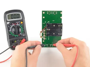
Multimeter Testing
What Is Multimeter Testing and Why Does It Matter?
Multimeter Testing refers to the use of a digital multimeter (DMM) to measure electrical characteristics such as voltage, resistance, current, continuity, and sometimes capacitance or diode behavior on a circuit board. By comparing measured values with the expected design values, engineers can determine whether a circuit is operating correctly and identify abnormal electrical paths.
A typical multimeter provides several useful testing modes. Continuity testing can determine whether two points are electrically connected. Resistance testing can help identify unintended shorts or open circuits. DC voltage testing can verify whether power rails are reaching the correct locations. Diode mode can also be useful when checking semiconductor junctions and certain protection circuits.
The key point is that a multimeter does not simply tell engineers whether a PCB is “good” or “bad.” It provides electrical evidence that can be used to narrow down the location and possible cause of a failure.
For example, if a power rail measures significantly lower than its expected voltage, the problem may be caused by an overloaded circuit, shorted component, damaged capacitor, or PCB defect. A resistance and continuity check can then help narrow the investigation.
How to Perform Multimeter Testing Step by Step
A structured testing sequence reduces unnecessary measurements and prevents technicians from overlooking basic problems.
1. Perform a Visual Inspection
Before using the meter, inspect the PCB carefully. Look for solder bridges, missing components, damaged pads, burnt areas, cracked components, lifted traces, contamination, and obvious mechanical damage.
Visual inspection is important because some manufacturing defects can be identified without electrical testing. Combining visual inspection with electrical measurements can significantly reduce troubleshooting time.
2. Check Ground and Power Connections
Start by identifying the main ground plane and power input. Confirm that the power supply is connected with the correct polarity and that the ground connection is reliable.
A continuity test between appropriate ground points can help determine whether the ground network is connected as intended. However, engineers should remember that a low resistance reading does not automatically indicate a defect because some PCB circuits naturally contain low-resistance paths.
3. Check for Possible Short Circuits
With the PCB powered off, use resistance or continuity mode to investigate suspicious connections between power and ground.
A very low resistance measurement between a power rail and ground can indicate a short circuit, although the expected resistance depends heavily on the circuit design. Some ICs, capacitors, and power circuits may naturally produce relatively low readings.
Therefore, measurements should always be compared with the schematic, known-good PCB, or expected design characteristics rather than interpreted in isolation.
4. Measure the Power Supply Voltage
After confirming that there is no obvious short, power the board and measure the voltage at the input and important power rails.
For example, if a circuit requires a 5 V input but only 1.2 V is measured, the problem may exist in the power supply, protection circuit, regulator, connector, or upstream PCB path.
Testing voltage at multiple points can help locate where the expected voltage disappears.
5. Check Continuity of Critical Traces
Important signal and power paths should be checked when an open circuit is suspected. Place the probes at both ends of the suspected connection and verify whether the electrical path is continuous.
This can identify problems such as broken traces, incomplete vias, defective connectors, or insufficient solder joints.
6. Compare Measurements With a Known-Good Board
When available, comparing a failed PCB with a known-good board can make troubleshooting much faster. Instead of relying only on theoretical values, engineers can compare resistance, voltage, and continuity at identical test points.
This approach is particularly useful when dealing with complex multilayer boards where several electrical paths may be interconnected.
What Problems Can Multimeter Testing Reveal?
The most useful aspect of electrical measurement is its ability to connect a visible failure with a potential physical cause.
| Problem | Possible Cause | Typical Testing Approach |
|---|---|---|
| No power | Open connection, connector issue, power supply failure | Voltage + continuity |
| Power rail short | Solder bridge, damaged component, PCB defect | Resistance |
| Signal missing | Broken trace, bad via, solder joint | Continuity + voltage |
| Unexpected voltage | Component failure or incorrect connection | Voltage measurement |
| Intermittent operation | Cracked solder joint or mechanical defect | Continuity + physical inspection |
| Excessive current | Short circuit or overloaded component | Current measurement |
However, a multimeter cannot identify every PCB problem. High-speed signal integrity issues, impedance variations, electromagnetic interference, subtle thermal problems, and some intermittent faults may require oscilloscopes, LCR meters, flying-probe testers, automated optical inspection, or other specialized equipment.
This is why the meter should be viewed as one part of a broader troubleshooting strategy rather than a universal diagnostic solution.
How Multimeter Testing Affects PCB Performance and Reliability
Electrical testing has an indirect but important relationship with PCB performance. Detecting manufacturing defects before shipment can prevent defective boards from entering system-level assembly, where troubleshooting becomes more expensive and time-consuming.
A short circuit may cause excessive current and localized heating. An open trace can interrupt a power or signal path. A poor solder connection may create intermittent electrical behavior. Even a small manufacturing defect can therefore affect functional performance and long-term reliability.
For PCB manufacturers, electrical verification is especially valuable for identifying process-related problems. Potential causes include incorrect drilling, insufficient copper plating, trace damage during etching, soldering defects, contamination, or unintended copper connections.
In my view, the most important lesson is that measurement should not stop when a defect is discovered. If multiple boards show the same abnormal result, the manufacturer should investigate the process behind the defect. Repeated failures are often evidence of a systematic manufacturing issue rather than isolated component damage.
What Are the Cost Factors of Multimeter Testing?
A basic multimeter is relatively inexpensive compared with many automated PCB inspection systems. Nevertheless, the total cost of electrical testing includes much more than the purchase price of the instrument.
Labor is often one of the biggest factors. Manual testing requires trained technicians who understand schematics, test points, expected values, and measurement limitations. Testing time also increases as PCB complexity increases.
Other cost factors include:
- Multimeter and probe quality
- Calibration and maintenance
- Technician training
- Test fixture or probe requirements
- Engineering analysis time
- Rework and repair costs
- Production downtime caused by troubleshooting
- Cost of defective boards discovered late in production
For small-volume or prototype PCB production, manual testing can be practical and flexible. For high-volume production, manufacturers may combine manual measurements with automated electrical testing to improve consistency and throughput.
The most economical strategy is not necessarily the cheapest testing method. A slightly higher inspection cost can be justified if it prevents large quantities of defective PCBs from reaching the customer.
Common Multimeter Testing Problems in PCB Manufacturing and Solutions
Electrical testing itself can also produce misleading results if the procedure is not properly controlled.
One common problem is incorrect probe placement. Measuring the wrong test points can produce a perfectly reasonable number that has no relationship to the actual failure. Clear test-point identification and engineering documentation can reduce this risk.
Another problem is incorrect interpretation of resistance measurements. A low resistance reading does not always mean that a short circuit exists. Parallel components, semiconductor devices, capacitors, and power circuits can all influence the measurement.
Inconsistent testing procedures can also create problems. Different technicians may use different test points, measurement ranges, or acceptance criteria. Standardized work instructions and defined test limits can improve repeatability.
For production environments, a practical solution is to establish a clear testing flow:
Visual Inspection → Power-Off Resistance Check → Continuity Check → Power-On Voltage Check → Functional Test → Root-Cause Analysis
This approach makes troubleshooting more systematic and helps manufacturers distinguish between PCB fabrication defects, assembly defects, and component-related failures.
Why Multimeter Testing Deserves More Attention in PCB Manufacturing
As PCB designs become denser and more electrically complex, troubleshooting becomes increasingly difficult. Fine-pitch components, high-density interconnects, multilayer structures, and smaller traces leave less room for manufacturing variation.
A board may look perfect under visual inspection while still containing an electrical defect. This is why electrical verification remains important even when advanced manufacturing equipment and automated inspection systems are available.
At the same time, engineers should avoid treating every abnormal measurement as a PCB manufacturing failure. A defective component, incorrect schematic, firmware problem, or external power supply can produce symptoms that appear to originate from the board.
The most effective approach is therefore to combine measurement data with the PCB layout, schematic, BOM, manufacturing records, and known-good samples.
How to Improve Multimeter Testing Efficiency
Several simple practices can make troubleshooting faster and more reliable.
First, define critical test points during PCB design rather than adding them only after a failure occurs. Accessible test points can dramatically simplify production testing and field maintenance.
Second, establish expected voltage and resistance ranges for important circuits. Technicians can then compare actual measurements with defined limits instead of relying on personal experience.
Third, keep records of recurring failures. If several production lots show similar resistance or voltage abnormalities, the data may reveal a process trend that would otherwise remain unnoticed.
Finally, use the multimeter as part of a layered quality-control system. Combining visual inspection, AOI, electrical testing, functional testing, and process monitoring provides much stronger coverage than relying on a single inspection method.
Conclusion
A non-working circuit board does not always require complicated diagnostic equipment. In many cases, a systematic electrical inspection can quickly narrow down the source of a problem. Voltage, resistance, and continuity measurements provide valuable information about power delivery, electrical connections, shorts, open circuits, and potentially defective components.
However, effective troubleshooting depends on more than simply placing two probes on a PCB. Engineers need to understand the circuit, select appropriate test points, establish reasonable measurement expectations, and compare results with reliable reference data.
From a manufacturing perspective, the bigger opportunity is to use troubleshooting data for continuous improvement. If the same electrical defect appears repeatedly, the goal should not simply be to repair the affected boards. The manufacturing process, design rules, materials, drilling, plating, etching, soldering, and inspection procedures should also be reviewed.
Ultimately, the value of a multimeter lies in turning an unexplained PCB failure into measurable information. When that information is combined with disciplined manufacturing controls, it can help reduce rework, improve production yield, protect product reliability, and give customers greater confidence in PCB quality.
FAQs
1. Can Multimeter Testing Find Every PCB Problem?
No. It is effective for many basic electrical problems, including shorts, open circuits, incorrect voltages, and continuity failures. High-frequency signal integrity, impedance, thermal behavior, and certain intermittent problems may require specialized instruments.
2. Can I Test a PCB With Power Applied?
Yes, voltage measurements normally require the PCB to be powered. However, resistance and continuity measurements should generally be performed with the circuit powered off. Using the wrong mode on a powered circuit can damage the meter or the PCB.
3. What Does a Low Resistance Reading Mean on a PCB?
A low resistance reading may indicate a short circuit, but it does not automatically prove that a defect exists. Components connected between the measurement points can naturally produce low resistance. The reading should be compared with the schematic or a known-good board.
4. Why Is Continuity Testing Important for PCB Manufacturing?
Continuity testing can help identify broken traces, incomplete connections, defective vias, connector problems, and certain soldering defects. It is particularly useful when a circuit fails because an electrical path is interrupted.
5. When Should a PCB Manufacturer Use More Advanced Testing?
Advanced testing should be considered when the PCB contains high-speed signals, complex power systems, dense interconnections, or reliability-critical circuits. Depending on the application, manufacturers may combine manual electrical measurements with flying-probe testing, automated electrical testing, AOI, X-ray inspection, and functional testing.

- Special PCB
- long board pcb
- Flexible PCBs
- Special PCB
- Express Printed Circuit Board
- Pcb Prototype
- LED PCB
- PCB
- Pcb Meaning
- Printed Circuit Board
- Pcb manufacturer
- Rigid pcb board
 Quote
 E-mail